
Imagine this scenario: You visit a local generating station that needs relay testing. They direct you to a switchyard relay house with microprocessor relays and test switches. The customer wants the relays tested, but the breakers are part of a bigger ring bus system that is powering loads to the city. The breakers cannot be tripped. What special considerations can you take to prevent causing incidental trips? Do you have a checklist of things to work through? What if the relay house is full of electro-mechanical relays instead? If special considerations are not taken, steps could be skipped that would lead to your routine workday becoming a nightmare. This article reviews the safety and operational concerns of real-life scenarios and describes steps and procedures to guide you through them.
The North American Electric Reliability Corporation (NERC) requires trip circuits and the operation of the relay itself to be validated. However, customers will still push towards relay testing without tripping associated circuit breakers and lockout devices. Perhaps they are meeting the NERC scheduling requirements, but they want their relays tested more often. You must prepare for these scenarios in advance because, if they take you by surprise, mistakes can be costly.
There are many reasons for such a request. The most common is a desire to maintain continuity of power. At a generating station, the load is the transmission line feeding the city grid or back-feeding the plant during the maintenance outage. If a mine site, the load could be a critical process that they do not want to interrupt. Maintaining the reliability of a ring bus system by not tripping critical ring bus breakers is another example.
RELAY HOT TESTING
In relay hot testing, the relays need testing, but the load must remain hot. As with any other hot testing, the primary concern is safety. Because the relay provides protection for the circuit, the question of how to maintain protection must be answered.
Scenario 1
At a generating station, the generator unit you are testing relays for is down and in a maintenance window, so there are no concerns about tripping the generator breaker. However, the trip circuit is also tied to switchyard breakers on a ring bus system that the customer does not want tripped. In this scenario, the safety concerns for the relay technician are low, but operational concerns must be considered.
Scenario 2
You visit a copper mining site to test relays for their electrowinning switchgear. The process is active and production is running, and the customer does not want this process interrupted while the microprocessor relays are tested. In this case, the breakers are right in front of you as you are testing, and they are closed and feeding load. There is a direct safety issue for you as well as an operational concern for the plant.
Safety Considerations
Electrical shock will always be a concern with relays as control power and trip circuit power can deliver electrical shocks. When relay hot testing is performed, there is the additional risk of an arc flash during a fault event, especially if your work is occurring right in front of the circuit breaker cubicle. Ask these questions:
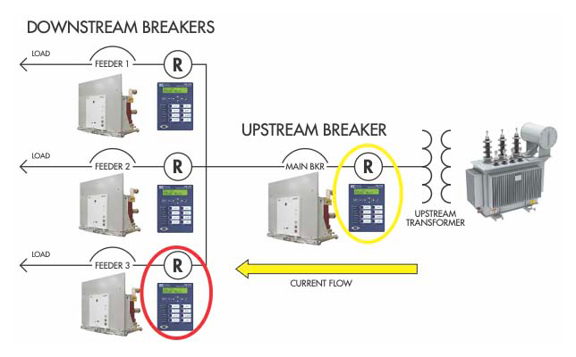
- Is there upstream protection? Talk to the customer and look over the one-line diagrams. There must be some continuity of protection in the unlikely case that a fault occurs while you are testing. If you are testing feeder breakers, the main breaker for the switchgear should provide you with upstream protection (Figure 1). If there is no main breaker, or you are testing the main breaker itself, this is especially dangerous. You will need protection on a different switchboard upstream. Talk to your manager for advice.
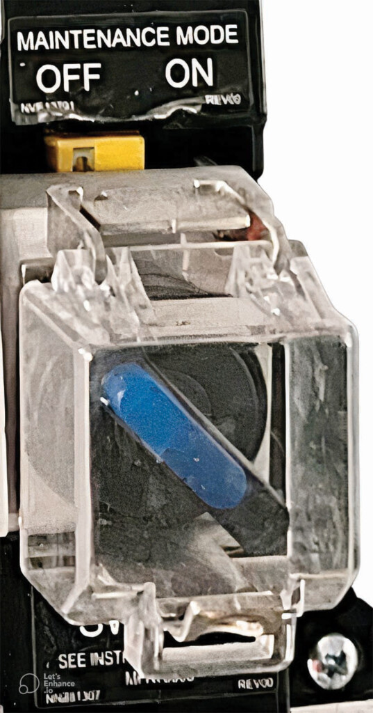
- Is there a maintenance mode switch? Maintenance mode switches (Figure 2), also known as RELT or arc flash reduction switches, temporarily lower the instantaneous setpoint while maintenance is performed. This mitigates the arc flash during a fault and protects the worker. The maintenance mode switch for the upstream circuit breaker must be turned on. Be sure to get the customer’s permission and return the system to normal after testing is completed.
- Is there a backup relay? Sometimes two relays will be protecting the load — a primary and a backup. This is the ideal scenario as you can test the primary relay while the backup provides continuous protection. When the primary relay has been restored to service, you can test the backup relay while the primary provides continuity of protection.
Operational Considerations
The customer has stated that they do not want the associated circuit breaker(s) tripped. That means that the trip circuit of the breaker must not be energized and any associated 86 Lockout devices cannot be rolled. The procedure is different for drawout relays vs. non-drawout relays.
Drawout Relays
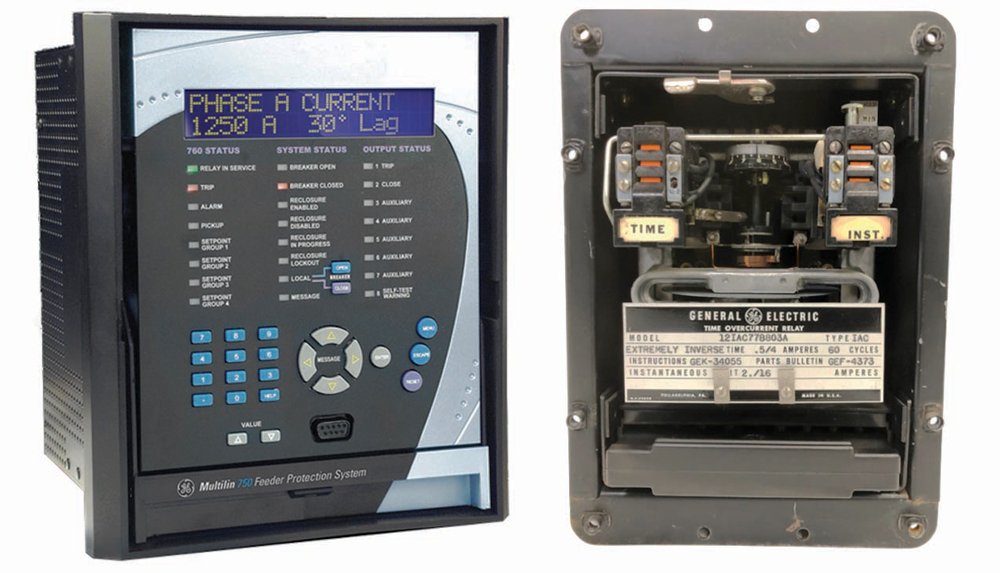
Drawout relays can be pulled from their cases and bench-tested. Examples include GE Multilin relays (Figure 3a), Circuit Shield relays, and electro-mechanical relays (Figure 3b). Before pulling a drawout relay from its case, take these steps:
- For microprocessor relays like Multilin, review the logic and make sure the failsafe contacts, which will energize a trip coil when power is lost to the relay, are not enabled. Motor relays are especially notorious for having failsafe logic. Failsafe contacts will energize a trip coil when power to the relay is lost.
- For Circuit Shield and electromechanical relays, look over the schematic drawings for the trip circuits to see if there are normally closed contacts in the circuit. Most electro-mechanical relay contacts will be set to normally open, but undervoltage relays are a popular exception.
- If failsafe logic is enabled or if normally closed relays (such as undervoltage relays) are to be tested, discuss with the customer and your manager. Testing may not be possible without de-energizing the load.
Non-Drawout Relays
With microprocessor relays that cannot be drawn out, (Schweitzer Engineering Laboratories aka SEL is a popular example), care needs to be taken to zero out the logic outputs before testing (see sidebar for detailed procedure). Start with these steps:
- Download settings to a file that can be saved on your computer before changing any settings in the relay.
- Zero out outputs before running any test or hooking up any test leads.
Trip Circuits
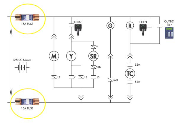
Trip circuits to the breaker can also be prevented from energizing by removing trip circuit fuses. Locate the breaker’s schematic drawing and identify any fuses that will de-energize the circuit completely and prevent power from reaching the trip coil (Figure 4). Review this information with the customer and ask them to pull fuses. Whenever possible, it is best to have the customer change the position of any breakers and pull any fuses because they own the equipment. This minimizes risk to you and lowers liability concerns if something goes wrong.
As-Found and As-Left Settings
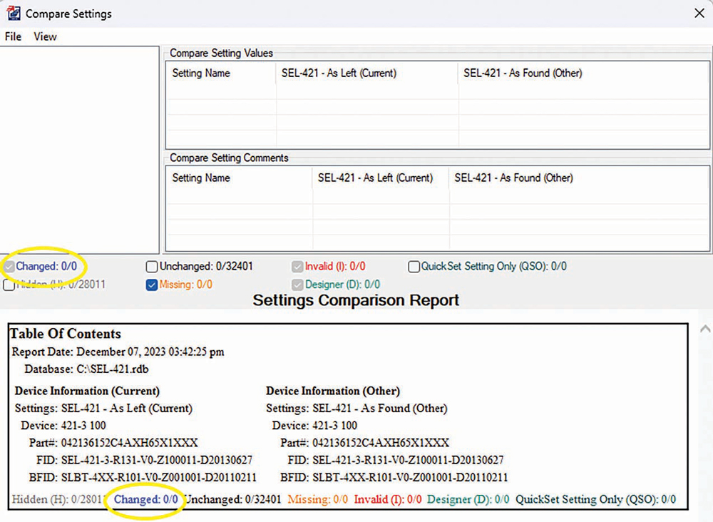
Because you are making changes to the relay settings file, it is important to be sure to upload the as-found settings file that you saved back into the relay when testing is complete. A good practice is to do another Read command after uploading the as-found settings and save that file as-left. Most microprocessor relay software includes a tool that allows you to do a comparison between two files. Compare the as-found and as-left settings to ensure there are no differences (Figure 5).
Testing with a Spare Output
Some relay technicians prefer to use a spare output while performing relay testing. This is a good idea in theory if the relay tech is concerned with overwriting settings in the relay and prefers not to do that for fear of making a mistake. While this concern is warranted, following the proper procedure for the as-found and as-left settings will achieve the desired outcome.
While using a spare output can sometimes be easier, especially if the test switches don’t contain the wiring for the trip contacts being used, this should be avoided because you are not testing the actual output that the customer is using. Imagine a scenario where you test the spare output and it works fine, but there is a problem with the actual trip output that the customer is using for the circuit breaker. You wouldn’t find the problem because you didn’t test it. Avoid this scenario. If the main trip output is wired to the test switch, it can be used with the test switch open if you make sure you are connecting to the relay side of the test switch.
Special Considerations for Relays with Fiber Optic Communications
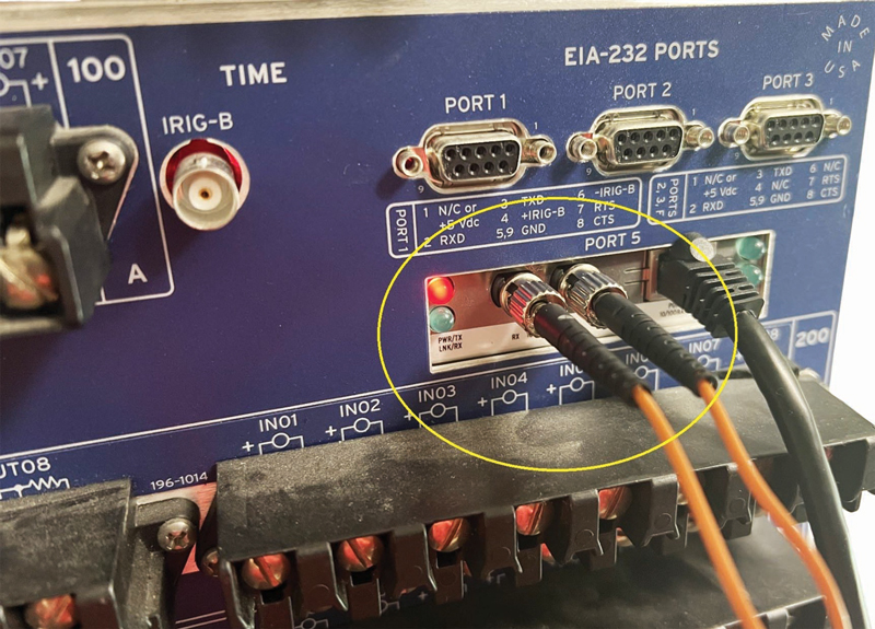
Proceed with caution if the relay being tested has fiber optic communication with another relay, such as a line differential relay or distance relay (Figure 6). Even if you zero out all the outputs on a line differential relay, the device will communicate with the relay on the other side of the transmission line via fiber and initiate a trip from the remote unit. If you encounter a relay connected to a remote relay via fiber, discuss options with the customer and your manager.
- One option is to remove the fiber optic cables and test each relay independently.
- Another option is to leave the fiber communication intact, but you will need to zero out outputs on both relays.
- Either option will require you to contact the transmission control center for your local utility to inform them of what is happening.
HOW TO ZERO OUTPUTS ON A MICROPROCESSOR RELAY
Microprocessor relays have logic that can be configured to prevent closing output contacts. When logic is asserted to zero (0), a normally open contact will be open, and when the logic is asserted to a one (1), a normally open contact will be closed.
To prevent the normally open trip circuit contacts from closing during testing, it is necessary to change the logic to zero (0) to prevent the trip circuit from energizing.
I use SEL relays for this example. In the SEL AcSELerator program, establish communication with the relay.
- Perform a READ command, save the settings file to your computer, and mark them as-found.
- Press Ctrl + T to bring up the terminal window.
- From the terminal window, type ACC and press enter.
- Enter the level 1 password. The default can be found in the manual.
- Type 2AC and press enter.
- Enter the level 2 password.
- Type SET L for setting the logic.
- SEL relays typically have outputs labeled OUT1, OUT2, or OUT101, OUT102, etc.
- The outputs will show logic such as TRIP or 50P1. To zero them out, change this logic by typing zero (0).
- The relay will also have a setting for failsafe contacts. When it prompts you to input for a failsafe, type N for No.
- When it prompts you to input for an output such as OUT101, type 0 to disable that output.
- Continue typing N for failsafe and 0 for OUT until all of the outputs have been entered.
- When you have finished, type END and press enter.
- When it asks you to save the settings, type Y and press enter.
- It should display the saved settings. If it does not, you can type SHO L.
The logic readout should be something like this:
Base Output Set
OUT101FS := N
OUT101 := 0
OUT102FS := N
OUT102 := 0
OUT103FS := N
OUT103 := 0
Slot C Output Set
OUT301FS := N
OUT301 := 0
OUT302FS := N
OUT302 := 0
OUT303FS := N
OUT303 := 0
OUT304FS := N
OUT304 := 0 - You will notice that when the outputs are properly zeroed out, it will read NO NO NO NO NO. This is a good way to remember this. If it doesn’t look like this, you didn’t do it right. Repeat the steps until it matches the above printout.
CONCLUSION
When visiting a customer site, the ideal scenario is that they are in a complete shutdown and tripping circuit breakers is permissible. Ideal scenarios don’t always happen in the field, however, so properly prepare for them in advance. Drawout relays are easy to pull out and bench test, but non-drawout relays are very common in the field, and it pays to have a procedure ready for them.
Properly zeroing out outputs is a good method to prevent tripping circuit breakers while testing microprocessor relays. This is a delicate and complex task. During my time in the field, this situation came up often. It always had a walking-on-eggshells feel to it because of how easy it would be to make a critical mistake. It is easy to get used to the routine of commissioning at a new site where nothing is energized, and tripping circuit breakers is not only permitted but encouraged.
Relay hot testing adds a stress component that will keep you on your toes. Be patient, keep a cool head, and follow a procedure. That will be a recipe for success in your relay testing experiences.

Christopher Ness is a Relay Applications Engineer at Megger, leveraging his extensive experience in the field of electric power systems protection, troubleshooting, and control systems. Before joining Megger, Christopher was a NETA IV certified technician at Vertiv. His professional journey includes tenures at manufacturing firms including Eaton, GE, and ABB. Christopher’s foundational expertise in electrical engineering was gained during his service in the US Navy, where he served as an electrician’s mate in the nuclear field, marked by a significant assignment on the nuclear aircraft carrier USS Nimitz.