

After a power or distribution transformer is disconnected from the power grid or when DC current is applied, such as when a routine winding resistance measurement test is performed, the transformer core is likely to have some remnant magnetism. This remnant magnetism will increase the magnitude of the already high inrush over current levels seen when a transformer is energized. This inrush current, which runs for a few cycles, reaches a maximum when the polarity of the half cycle is the same as the polarity of the remnant magnetism, and it could damage the transformer itself or other components connected to it. To avoid this undesirable effect, a transformer should be demagnetized after testing is complete and before being re-energized. This article looks at the influence of residual magnetism on the inrush current, the influence of residual magnetism on electrical routine and diagnostic measurements, and finally, the art of accurate demagnetization.
MAGNETIC CIRCUITS
A magnetic circuit can be compared with an electric current in which EMF, or voltage, produces a current flow. The ampere-turns (NI) or the magnetomotive force (Fm or mmf) will produce a magnetic flux Φ (Figure 1).
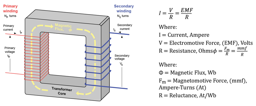
The mmf can be compared with EMF, and the flux (Φ) can be compared to current. EMF is to mmf and current is to flux, so too, resistance is to reluctance. The equation shown is the mathematical representation of magnetomotive force derived using Ohm’s Law: I = V/R. Reluctance will be affected by the length of the coil, the permeability of the magnetic material, and the cross-sectional area of the coil.
BH MAGNETIZATION CURVE
The flux density, flux intensity, or BH magnetization curve seen in Figure 2 shows how much flux density (B) results from increasing the flux intensity (H). The curves shown are for two types of soft iron cores plotted for typical values.
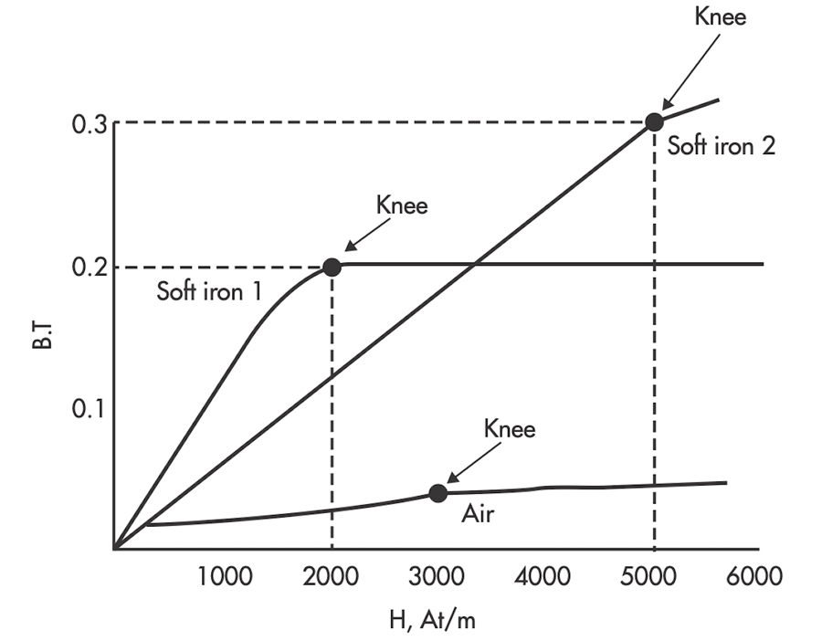
The curve for soft iron 1 shows that flux density B increases rapidly with an increase in flux intensity H before the core saturates, or develops a “knee.” Thereafter, an increase in flux intensity H has little or no effect on flux density B. Soft iron 2 needs a much larger increase in flux intensity H before it reaches its saturation level at H = 5,000 At/m, B = 0.3T.
HYSTERESIS
When current in a coil reverses direction many times per second, hysteresis can cause considerable loss of energy. Hysteresis is defined as “a lagging behind.” The magnetic flux in an iron core lags the magnetizing force. The hysteresis loop is a series of curves that show the characteristics of a magnetic material, as seen in Figure 3. Opposite directions of current will result in opposite directions of flux intensity shown as +H and -H. Opposite polarities are also shown for flux density as +B or -B.
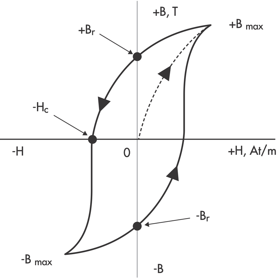
Current starts at the center (zero) when unmagnetized. Positive H values increase B to the saturation point, or +Bmax, as shown by the dashed line. Then H decreases to zero, but B drops to the value of Br due to hysteresis. By reversing the original current, H now becomes negative. B drops to zero and continues to -Bmax. As the -H values decrease (less negative), B is reduced to –Br when H is zero. With a positive swing of current, H once again becomes positive, producing saturation at +Bmax. The hysteresis loop is completed. The loop does not return to zero because of hysteresis.
The value of +Br or -Br, which is the flux density remaining after the magnetizing force is zero, is called the retentivity of that magnetic material. The value of -Hc, which is the force that must be applied in the reverse direction to reduce flux density to zero, is called the coercive force of the material. The greater the area inside the hysteresis loop, the larger the hysteresis losses.
REMNANT (RESIDUAL) MAGNETISM
The magnetic core of a power transformer is very often found in a magnetized state. This magnetism is called remnant or residual magnetism, and it has undesirable effects on transformer operation. Remnant magnetism can have several causes:
- Disconnecting a transformer from service. Since the voltage is never in phase with the current, and the current is interrupted at point zero, there is a certain voltage at that point, and the corresponding flux would remain in the core.
- High fault currents. Remnant magnetism is a common consequence of high fault currents. The transformer may withstand the fault current due to relays clearing the fault, but some magnetism resulting from the current remains in the transformer core.
- DC testing. A winding resistance measurement on a power transformer is performed using DC current in the order of 10% rated current of the winding under test. This test is normally performed as the very last test due to the effects of remanence on other AC test results.
Proper winding resistance technique — to speed up the process of obtaining a stabilized result — requires that the magnetic core be brought into saturation. Having DC current at that level magnetizes the transformer core. Once the test is finished, switching the current off, the winding is discharged, but it is not demagnetized.
EFFECTS OF REMNANT MAGNETISM
Remnant magnetism contributes to a high amplitude of inrush current at start-up. Inrush current is a form of overcurrent that occurs during the energization of a transformer. It is a large transient current that is caused by part-cycle saturation of the magnetic core of the transformer.
When an electrical power transformer is switched on from its primary side, while keeping its secondary circuit open, it acts as a simple inductance. When an electrical power transformer runs normally, the flux produced in the core is in quadrature with the applied voltage as shown in Figure 4. That means the flux wave will reach its maximum value 1/4 cycle after the voltage wave reaches its maximum value. Hence as per the waves shown in the figure, at the instant when the voltage is zero, the corresponding steady state value of flux should be at negative maximum.
Practically, however, it is not possible to have flux at the instant of switching on the supply of the transformer. This is because there will be no flux linked to the core prior to switching on the supply. The steady-state value of flux will only be reached after a finite time, depending on how fast the circuit can take energy. This is because the rate of energy transfer to a circuit cannot be infinite. So the flux wave will be initiated from the same origin as the voltage waveform at the time of switching on the transformer. Transformer cores are generally saturated just above the maximum steady state value of flux.
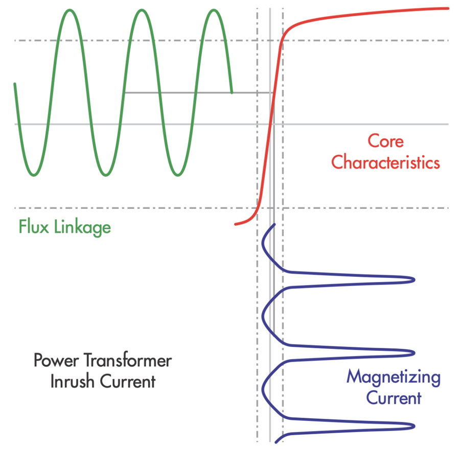
But during switching the transformer on, the maximum value of flux will jump to double its steady state maximum value (Figure 5). After the steady state maximum value of flux, the core becomes saturated, and the current required to produce the remainder of the required flux will be very high. So the transformer primary will draw a very high peak current from the source, which is called magnetizing inrush current in a transformer or simply inrush current in a transformer.
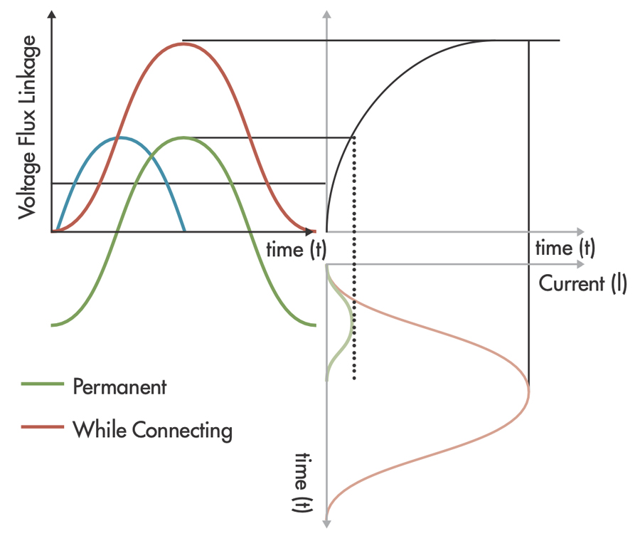
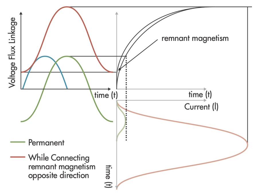
If, during re-energizing, the initial value of flux differs from the prospective flux due to remnant magnetism, a DC offset of the flux-linkage will be caused and a higher-than-rated peak value will be present. This results in an inrush current that may be several times the value of the normal current (Figure 6).
Next, let’s look at the possibility of mechanical damage to a transformer’s active parts. The windings are exposed to mechanical stress proportional to the square of the current. Mechanical shocks caused by overcurrent surges may damage the coils and release the clamping pressure. This would eventually lead to loose windings and a transformer failure.
Power Quality
Power quality problems may arise due to remnant magnetism at the time of start-up. If remanence is present, high resonant harmonic overvoltages and voltage sags are all present when the transformer operates in the first few cycles after the energization.
Relay Operation
During incorrect operations of protective relays, the protective devices for overloads and internal faults may falsely operate and disconnect the transformer from the electrical system. Figure 7 shows a situation where the inrush current was switched off after five cycles.
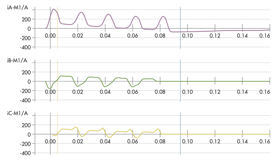
The A phase current exceeded 400 A in the first half cycle, while the other two phases show great asymmetry and the presence of higher harmonics in the current waveform. The consequence of this unnecessary relay operation is the need for another subsequent powering of the transformer, introducing another mechanical shock to the unit.
Routine Tests
In the event of a fault or during routine tests, various electrical diagnostic techniques can be used to analyze the condition of a transformer. Residual magnetism influences certain diagnostic measurements in such a way that reliable and meaningful analysis becomes nearly impossible. In particular, when performing excitation current measurements or sweep frequency response analysis for localization of faults in the core, residual magnetism may have such a negative effect that test results become unsolvable and useless.
DEMAGNETIZATION METHODS
Removal of remnant magnetism during start-up will extend transformer life by avoiding unnecessary stresses during start-up. Removing remnant magnetism prior to condition assessment tests will also render more reliable test results. There are three methods for removing remnant magnetism from power transformers:
- Variable voltage constant frequency source (VVCFS)
- Constant alternating voltage with decreasing time (CAVDT)
- Decreasing amplitude of an alternating polarity DC current (DAAPC)
Variable Voltage Constant Frequency Source
Variable voltage constant frequency source (VVCFS) is the best method. It is performed in the factory and requires a very large energy source. It is impractical for field operation because it requires a power frequency (50 or 60Hz) source powerful enough to magnetize the magnetic core. Another requirement is the ability to control and slowly reduce the applied voltage. By reducing the voltage and current from the operating level down to zero, the core is demagnetized. This is impossible to do in the field on even a medium-sized power transformer due to the large VA requirement of the test set.
Constant Alternating Voltage with Decreasing Time (CAVDT)
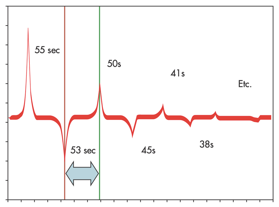
IEEE Std. 62–1995, Guide for Diagnostic Field Testing of Electric Power Apparatus (Section 6.1.3.5) directs one to alternate the polarity of a fixed voltage with decreasing application time per alternation of polarity. This is the constant alternating voltage with decreasing time (CAVDT) method (Figure 8). The principle of this method is to neutralize the magnetic alignment of the core iron by applying a direct voltage of alternate polarities to the transformer winding for decreasing intervals. The interval is usually determined when the demagnetizing current reaches a level slightly lower than the previous level, at which time the polarity of the voltage is reversed. The process is continued until the current level is zero.
On three-phase transformers, the usual practice is to perform the procedure on the phase with the highest exciting current reading. In most cases, experience has demonstrated that this procedure is sufficient to demagnetize the whole core. The explanation is clear: With decreasing time, you should obtain a slightly lower magnitude of the current. However, this is easier said than done.
With applied fixed voltage, once the current reaches the knee-point of the saturation curve, it changes too fast to manually control with precision. Experience has shown that improper procedure very often caused other core legs to become magnetized while one was being demagnetized. As shown here, the proper time sequence for diminishing current magnitude should be after the first sequence reaching the amplitude of 25 A at 55, 53, 50, 45, 41, 38… seconds. Note that at lower current levels, we may be talking fractions of a second.
Decreasing Amplitude of an Alternating Polarity DC Current (DAAPC)
Modern electronically controlled DC test instruments can control the amplitude of the applied current with high precision. Applying the decreasing amplitude of an alternating polarity DC current (DAAPC) method (Figure 9), they can be programmed to perform polarity reversal and automatic demagnetization of the power transformer magnetic core. The DAAPC method is the engineering approach to the IEEE standard directive to alternate polarity and lower the flux in the magnetic core by controlling the current amplitude in each step. The value of the initial amplitude is not important if saturation is reached on all three legs of the magnetic core.
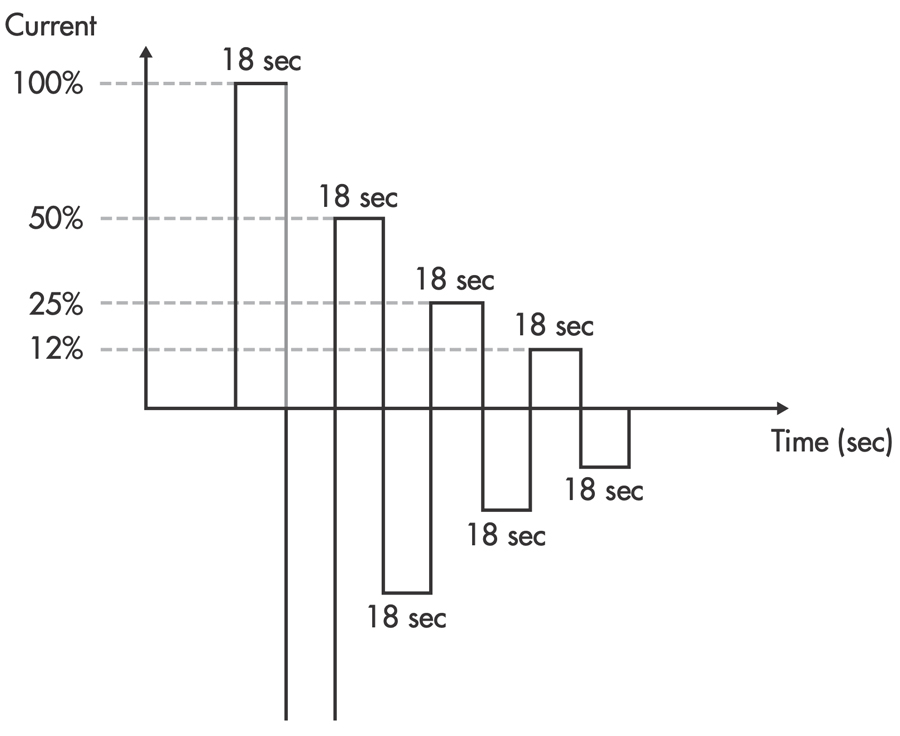
Following initial current charging and discharging, the next alteration is of 50% magnitude. When reached, discharge is initiated, and the steps go on in succession until the very small value of ampere-turns is applied as the very last step.
CONCLUSION
Magnetism and magnetic induction are fundamental principles of how and why a transformer operates. However, in situations where significant remnant magnetism is present in the transformer core, efforts must be taken to demagnetize it prior to re-energization.
Remnant magnetism remaining in the core can generate high overcurrents when the transformer is re-energized. Modern electronically controlled DC test instruments have made this demagnetization process easy to perform in the field using the decreasing amplitude of an alternating polarity DC current (DAAPC) technique. Applying this technique prior to re-energization will help ensure reliable performance and good health of your transformer.

Thomas Sandri is Director of Training Services at Protec Equipment Resources, where his responsibilities include the design and development of learning courses. He has been active in the field of electrical power and telecommunications for over 35 years. During his career, Tom has developed numerous training aids and training courses, has been published in various industry guides, and has conducted seminars domestically and internationally. Thomas supports a wide range of electrical and telecommunication maintenance application disciplines. He has been directly involved with and supported test and measurement applications for over 25 years and is considered an authority in application disciplines including insulation system analysis, medium- and high-voltage cable, and partial discharge analysis, as well as battery and DC systems testing and maintenance. Tom received a BSEE from Thomas Edison University in Trenton, New Jersey.