As time progresses and a cable system ages, the system’s bulk dielectric strength degrades. During this aging process, artifacts such as water trees, delamination, voids, and shield corrosion raise the local stress placed on the cable during normal operation. The exact way in which the strength of a device degrades will depend upon many factors including voltage, thermal stresses, maintenance practices, system age, cable system technology and materials, and environment.
For years, high-voltage direct current (DC) testing had been the traditionally accepted method for judging the serviceability of medium-voltage cables. DC high-potential tests have worked well for conducting dielectric strength and condition assessment tests on paper insulated lead covered (PILC) cable. When cable materials began to change and plastic insulated cables were first introduced in the 1960s, little was known about the overall aging characteristics of the new materials, and DC therefore continued to be the preferred method of testing.
As time moved on, plastic insulated cables became more abundant, and as they aged, they began showing effects of service age. DC continued to be the dominant test, but concerns began to grow over the effectiveness of this test. In the early 1990s, reports began to surface indicating that DC high-potential testing could be to blame for latent damage experienced by extruded medium-voltage cable insulation.
As insulation materials continue to change and improve and as reliability demands grow, testing methods have been developed that provide a better indication of the integrity of cables, splices, and terminations. To use these methods effectively, the operator must understand the mechanisms of aging and failure in cable systems. It is also important to understand testing techniques and have the ability to diagnose test results. It is equally important for trained personnel to be thoroughly familiar with the fundamentals of power cable design, operation, and maintenance.
This article reviews the evolution of testing methods and philosophies over the past 30-plus years. The intended application of each technique along with the advantages and limitations of the technique will be reviewed providing the knowledge necessary to develop an effective cable testing program.
SIX BASIC LAYERS OF MV CABLE CONSTRUCTION
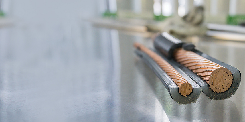
In a typical medium-voltage cable, copper or aluminum wires (either stranded or solid) are used as conductors (Figure 1). These conductors are covered with an extruded polymeric stress-control layer made of semi-conductive compounds, often referred to as the conductor shield. The insulation layer immediately surrounds and is fully bonded with the conductor shield. An insulation shield encases the insulation and, in some cases, may be composed of the same semi-conductive material as the conductor shield. The copper neutral wires or tape are wound around the insulation shield and are usually covered with a thermoplastic polyethylene jacket for mechanical protection from the external environment and to reduce moisture intrusion into the cable, all of which can cause premature cable failure.
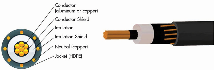
Figure 1: Medium-Voltage Cable Layers
Conductor Strand Types
Various conductor strand types are commonly used in cable construction. The various types provide advantages in certain applications by either reducing the diameter of the cable or by lowering total AC resistance for a given cross-sectional area of conducting material.
- Concentric strand. A concentric stranded conductor (Figure 2) consists of a central wire or core surrounded by one or more layers of helically laid wires. Each layer after the first has six more wires than the preceding layer. In compact stranding, each layer is usually applied in a direction opposite to that of the layer under it.
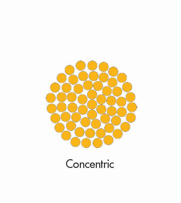
Figure 2: Concentric Strand
- Sector conductor. A sector conductor (Figure 3) is a stranded conductor with a cross-section in approximately the shape of a sector of a circle. A multiple-conductor insulated cable with sector conductors has a smaller diameter than the corresponding cable with round conductors.
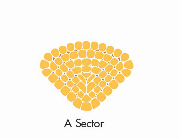
Figure 3: Sector Conductor
- Segmental conductor. A segmental conductor (Figure 4) is a round, stranded conductor composed of three or four sectors slightly insulated from one another. This construction has the advantage of lower AC resistance due to increased surface area and skin effect.
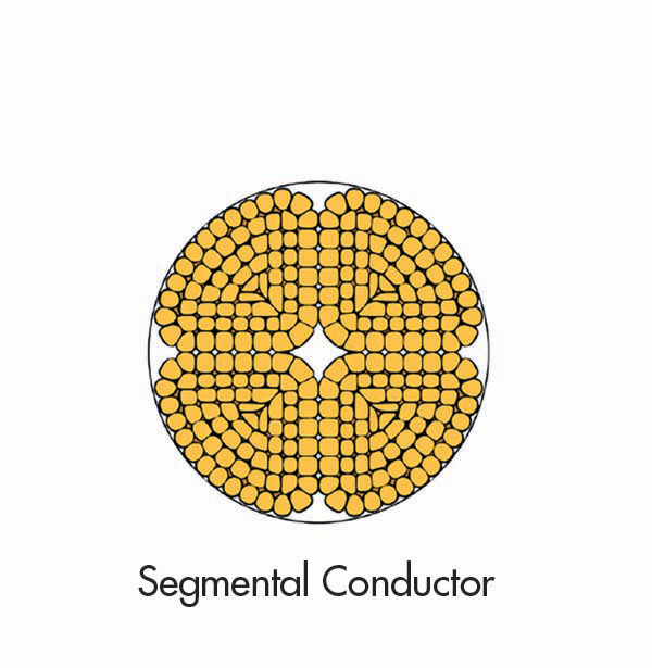
Figure 4: Segmental Conductor
- Compact strand. A compact stranded conductor (Figure 5) is a round or sector conductor having all layers stranded in the same direction and rolled to a predetermined ideal shape. The finished conductor is smooth on the surface and contains practically no interstices or air spaces. This results in a smaller diameter.
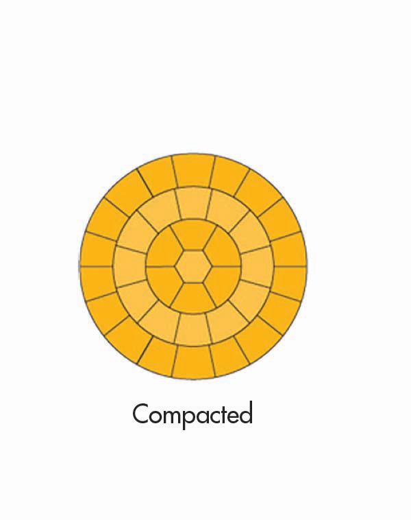
Figure 5: Compact Strand
Conductor Shield
The cable conductors are covered with an extruded polymeric stress-control layer made of semi-conductive compounds, often referred to as the conductor shield (Figure 6). The conductor shield isolates the cable insulation from any air surrounding the conductor strands. This is very important since air gaps will lead to ionization and partial discharge activity that will prematurely fail the insulation.
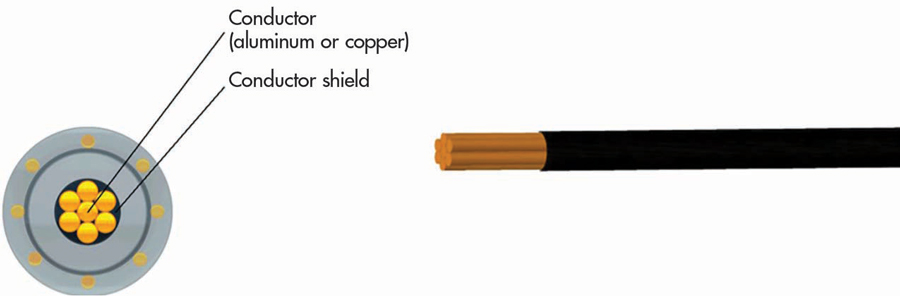
Figure 6: Conductor Shield
Insulation Materials
Comparing the dielectric losses of various insulation types (Table 1), we can see that polyethylene (PE) and cross-linked polyethylene (XLPE) offer the lowest dielectric losses. Paper/oil (PILC) has low to medium dielectric losses and ethylene propylene rubber (EPR) offers the highest dielectric losses. This comparison of materials also shows that PE and XLPE have sensitivity to water contamination (treeing) while EPR offers relatively low sensitivity to water contamination.
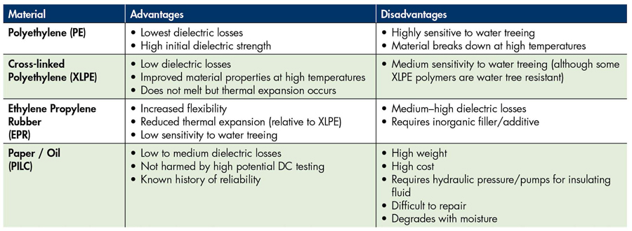
Table 1: Insulation Materials Insulation Shield
An understanding of the insulation material plays a key factor in the testing of cable and analysis of test results. When testing hybrid or mixed circuits, insulation with higher dielectric loss may mask the true condition of the cable section with lower dielectric losses.
Insulation Shield
The insulation shield encases the insulation and, in some cases, may be composed of the same semi-conductive material as the conductor shield (Figure 7). It serves a similar purpose as the conductor shield and shields the insulation from air that might cause ionization and partial discharge activity.
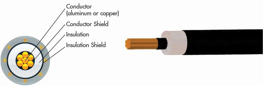
Figure 7: Insulation Shield
The purposes of the insulation shield are to:
- Obtain symmetrical radial stress distribution within the insulation.
- Eliminate tangential and longitudinal stresses on the surface of the insulation.
- Exclude from the dielectric field those materials such as braids, tapes, and fillers that are not intended as insulation.
- Protect the cables from induced or direct over-voltages. Shields do this by making the surge impedance uniform along the length of the cable and by helping to attenuate surge potentials.
Cable Shielding
Medium- and high-voltage power cables in circuits over 2,000 volts usually have a shield layer of copper or aluminum tape or conducting polymer. If an unshielded insulated cable is in contact with earth or a grounded object, the electrostatic field around the conductor will be concentrated at the contact point, resulting in corona discharge and eventual destruction of the insulation. Leakage current and capacitive current through the insulation present a danger of electrical shock. The grounded shield equalizes electrical stress around the conductor and diverts any leakage current to ground. Stress-relief cones should be applied at the shield ends, especially for cables operating at more than 2 kV to earth.
Several different types of shields are commonly used for medium-voltage cable applications. These shielding styles include:
- Tape-shielded (also called ribbon-shielded). Tape shields (Figure 8) over ethylene propylene rubber (EPR) insulation have been a favored power cable construction for years. The way the tape is wrapped can deliver significant reliability and performance benefits. The overlap of the tape windings is a key design feature in helical-tape construction. The Insulated Cable Engineers Association (ICEA) recommends a minimum tape overlap of 10%. However, extra overlap delivers increased short-circuit capacity and better mechanical reliability.
Caution should be taken during installation of this style cable. If a tape-shielded cable is bent too sharply or pulled around bends with too much tension, the tape windings may separate, and the tape can buckle when the cable straightens out. The buckling can damage the underlying insulation shield. In a conduit, the damage is invisible, and even in a cable tray, the cable jacket may conceal the condition. What’s worse, most electrical proof tests performed in the field will not reveal this kind of damage.
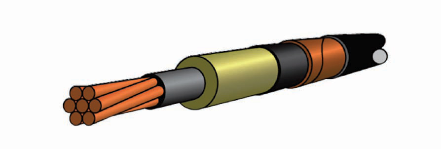
Figure 8: Tape-Shielded Cable
- Wire-shielded (also called concentric neutral). This cable offers the same construction as tape-shielded cable except for the different metallic shield layer (Figure 9). It is often considered interchangeable with tape-shielded cable and is very common in utility applications. When concentric neutral cables are specified, the concentric neutrals must be manufactured in accordance with the Insulated Cable Engineers Association (ICEA) standards. These wires must meet ASTM B3 for uncoated wires or ASTM B33 for coated wires.
These wires are applied directly over the nonmetallic insulation shield with a layer of not less than six or more than ten times the diameter of the concentric wires.
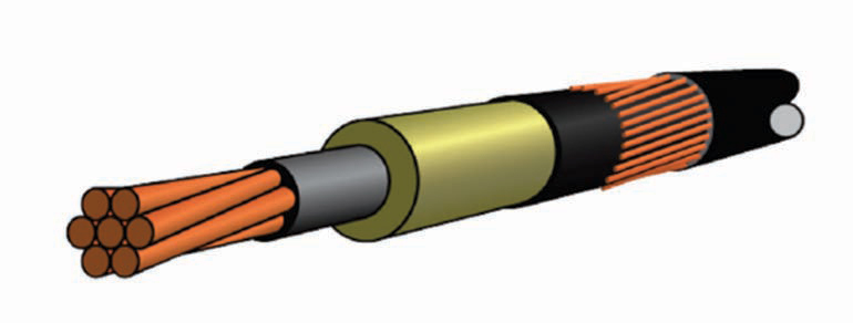
Figure 9: Wire-Shielded Cable
- UniShield® (a registered trademark of BICC Cables). Note the “Uni” in the name, which refers to the outer three layers being combined into a single layer: insulation shield, which also functions as a jacket, with metallic drain wires imbedded into the jacket to form a single functional layer (Figure 10).
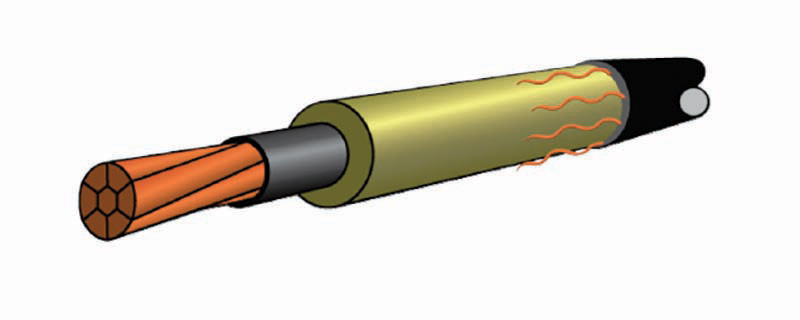
Figure 10: UniShield Cable
- PILC, paper-insulated, lead-covered cable. The paper insulation is impregnated with oil which must be kept contained within the cable by use of a lead jacket (Figure 11).
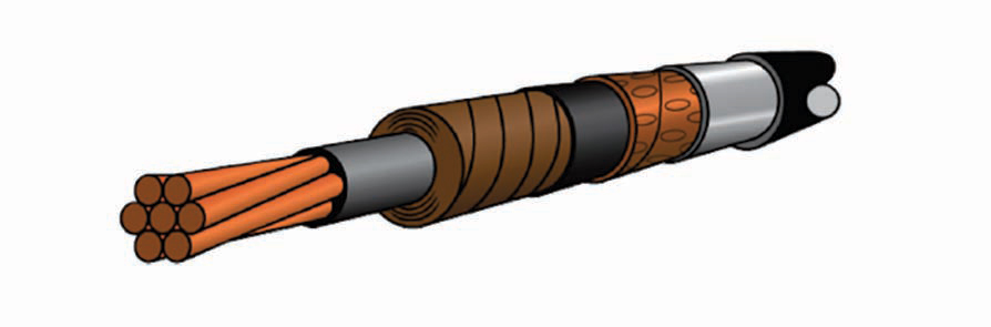
Figure 11: Paper-Insulated Lead-Covered Cable
CABLE AGING
A power cable fails when local electrical stresses are greater than the local dielectric strength of the dielectric material(s). Reliability and the rate of failure of the whole cabling system depend on the difference between the local stress at any given point in the system and the local strength at that point. Failure of the dielectric results in an electrical puncture or flashover at the location of the degraded dielectric. This flashover can occur between two dielectric surfaces, such as cable insulation and joint insulation, or it can occur as an external flashover at the cable terminations. A cable failure can occur because of the normally applied 50/60 Hz voltage or during a transient voltage such as lightning or switching surges.
As time progresses and the cable system ages, the bulk dielectric strength degrades. The main aging factor of extruded dielectric cable is electrical, although under abnormal situations, thermal aging can be significant. The electrical aging mechanisms — partial discharge, electrical treeing, water treeing, and charge injection — occur at contaminants, defects, protrusions, and voids and thus tend to be localized.
Looking at specific mechanisms, excessive electrical stress or bulk deterioration of the insulation can occur because of:
Manufacturing Imperfections
- Voids
- Contaminants in insulations
- Poor application of shield material
- Protrusions on the shields
- Poor application of jackets
Poor Workmanship
- Cuts
- Contamination
- Missing applied components or connections
- Misalignment of accessories
Aggressive Environment
- Chemical attack
- Transformer oil leaks
- Floods
- Petrochemical spills
- Neutral corrosion
Wet Environment
- Bowtie trees
- Vented water trees
- High rates of corrosion
- Can reduce dielectric properties
Overheating
- Excessive conductor current for a given environment and operating condition (global)
- Proximity to other cable circuits for short distances (local)
Mechanical
- Damage during transportation, typically localized
- Excessive pulling tensions or sidewall bearing pressures, either localized or global
- Damage from dig-ins, typically localized
Water Ingress
- Normal migration through polymeric materials
- Breaks in seals or metallic sheaths
Water Trees
Water trees, sometimes called electrochemical trees, have basic characteristics different than electrical trees. Electrical trees are characterized by the occurrence of partial discharge and require high electric stress to initiate, then rapidly lead to catastrophic dielectric failure. Water trees can be initiated at much lower dielectric stress and grow very slowly. These trees are associated with no measurable partial discharge and can completely bridge the insulation from conductor to shield without dielectric breakdown. Although breakdown does not occur, dielectric strength is greatly reduced. This is particularly true with regards to the direct current (DC) breakdown value.
Water tree degradation is a major problem for medium-voltage extruded dielectric cables, particularly service-aged XLPE cables. It is perhaps the worst degradation process of the polymeric insulation that contributes to the failure of the cable.
Water trees are formed and grow in the presence of moisture, impurities or contamination and the electric field over time. There are generally two types of water trees (Figure 12): bow-tie trees and vented trees.
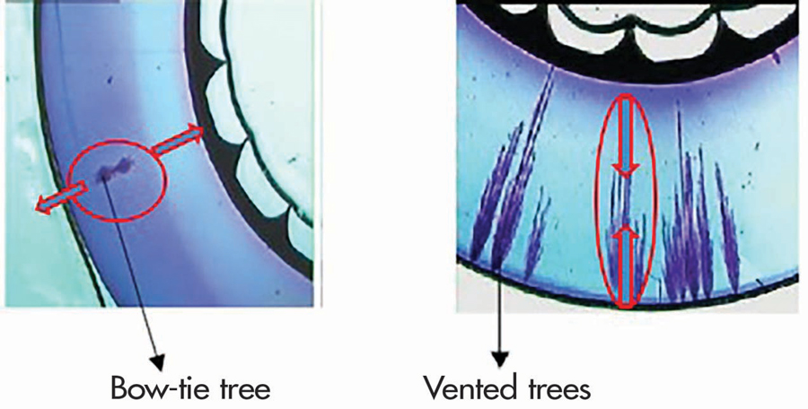
Figure 12: Types of Water Trees
Bow-tie trees are water trees that grow from the insulation outwards towards the surfaces of the insulation. These trees grow in the direction of the electric field in both directions, towards the two electrodes. Bow-tie trees have faster initial growth rate compared to vented trees. Bow-tie trees are, however, not capable of growing to large sizes and usually do not grow to a size significant enough to cause failure of the insulation.
Vented trees are water trees that grow from the surface of the polymer inwards into the insulation system. These trees will also grow in the direction of the electric field. Vented trees have a lower initial growth rate compared to bow-tie trees; however, vented trees can grow right through the entire insulation thickness.
Electrical Trees
The cumulative effect of partial discharges within solid dielectrics is the formation of numerous, branching partially conducting discharge channels, a process called electrical treeing (Figure 13). Repetitive discharge events cause irreversible mechanical and chemical deterioration of the insulating material. Damage is caused by the energy dissipated by high-energy electrons or ions, ultraviolet light from the discharges, ozone attacking the void walls, and cracking as the chemical breakdown processes liberate gases at high pressure.

Figure 13: Electrical Tree
The chemical transformation of the dielectric also tends to increase the electrical conductivity of the dielectric material surrounding the voids. This increases electrical stress in the unaffected gap region, accelerating the breakdown process.
CABLE TESTING OPTIONS
The Insulated Conductor Committee of the IEEE Power & Energy Society has divided test methods or philosophies into two fundamental categories: Type 1 field tests and Type 2 field tests.
Type 1 tests are intended to detect defects in the insulation of the cable system to improve service reliability after the defective part is removed and appropriate repairs are performed. The following tests are usually achieved by applying moderately increased voltages across the insulation for a prescribed duration of time. Such tests are categorized as pass/fail.
- Insulation resistance (under voltage)
- DC high potential: IEEE Std. 400.1, Guide for Field Testing of Laminated Dielectric, Shielded Power Cable Systems rated 5 KV and Above with High Direct Current Voltage and IEEE Std. 400.5, IEEE Guide for Field Testing of DC Shielded Power Cable Systems Rated 5 kV and Above with High Direct Current Test Voltages
- VLF high potential: IEEE Std. 400.2, Guide for Field Testing of Shielded Power Cable Systems Using Very Low Frequency
- High potential power frequency: typically considered a factory test and not a field test
Type 2 tests are intended to provide indications that the insulation system has deteriorated, hence, termed diagnostic tests:
- Dissipation factor (tan delta) testing: IEEE Std. 400.2, Guide for Field Testing of Shielded Power Cable Systems Using Very Low Frequency (VLF)
- Partial Discharge: IEEE Std. 400.3, Guide for Partial Discharge Testing of Shielded Power Cable Systems in a Field Environment
- Damped alternating current: IEEE Std. 400.4, IEEE Guide for Field Testing of Shielded Power Cable Systems Rated 5 kV and Above with Damped Alternating Current (DAC) Voltage
- Isothermal relaxation current test
- Return voltage
IEEE further categorizes cable testing into three areas:
- Installation tests. Field tests conducted after cable installation is complete, but before splicing or terminating occurs. The test is intended to detect shipping, storage, or installation damage.
- Acceptance tests. Field tests made after cable system installation, splicing, and terminations are completed, but before the cable system is placed in normal service. The tests are intended to further detect installation damage and to show any gross defects or errors in installation of the various system components.
- Maintenance tests. Field tests made during the operating life of a cable system. They are intended to detect deterioration of the system and to check the serviceability so that suitable maintenance procedures can be initiated.
UNDER VOLTAGE TESTING WITH DIRECT CURRENT
Under voltage tests performed with direct current (DC) are typically performed with a test set referred to as a megohmmeter. Since these tests use voltages under the rating of the insulation being tested, the test is a non-destructive test and does not produce any of the ill effects associated with high-voltage DC testing that we will discuss later in this article.
The traditional insulation resistance test is the simplest way to gain an overall indication of the condition of the insulation. Although the insulation resistance (IR) test can be applied as a simple Type 1 or go/no-go test, it can also be used to give more extensive diagnostic information. Type 2 or diagnostic insulation tests electrically stimulate the insulation and measure the response of the insulation to that stimulus. Depending on that response, we can draw some conclusions about the condition or heath of the insulation.
The test current in the body of the cable insulation can be split into three components:
- Capacitive current is initially large but goes to zero as the test piece is charged.
- Polarization current is caused by charges in the insulation material moving under the effect of the electric field or by molecular di-poles lining themselves up with the applied field (orientation polarization). It is greatly affected by moisture or contamination in the insulation, as the water molecule has additional orientation polarization. This process takes much longer than capacitive charging.
- Steady leakage current through the insulation, which is usually represented by a very-high resistor in parallel with the capacitance of the insulation.
Spot Test
The spot reading test is the simplest of all insulation tests. Test voltage is applied for a short but specific period of time (typically 1–2 minutes) as any capacitive charging current will usually have decayed by this time. A reading is then taken. On longer cables offering increased capacitance, the time for the capacitive charging current may be significantly increased. The reading can then be compared to the minimum installation specifications. Spot readings can be performed as part of an inspection or as part of troubleshooting and can be used as a simple good/bad indicator.
Spot test readings can also be trended against previously obtained values. However, insulation resistance is highly temperature dependent, and thus the results should be corrected to a standard temperature.
If the insulation resistance reading is high and the reading increases or remains steady during the test, the insulation is in good condition. As the capacitance current and absorption current decreases, insulation resistance increases. If the insulation resistance reading decreases during the test, the cable insulation is probably wet or otherwise in bad condition. If the final value of resistance is low (or the current is high), the cable insulation is in poor condition.
Time Resistance Test (Polarization Index/Dielectric Absorption)
A valuable property of insulation is that insulation charges during a test. The polar DC field applied by the megohmmeter causes realignment of the insulating material on the molecular level, as dipoles orient themselves with the field. This movement of charge constitutes a current. Its value as a diagnostic indicator is based on two opposing factors: The current dies away as the structure reaches its final orientation, while leakage promoted by deterioration passes a comparatively large, constant current. The net result is that leakage current is relatively small in good insulation, and resistance rises dramatically as charging goes to completion. This changing resistance provides diagnostic information related to the degree of degradation of the insulation (Figure 14). Deteriorated insulation will pass relatively large amounts of leakage current at a constant rate for the applied voltage. This will flood out the charging effect and will show little-to-no change in resistance value.
Time-resistance test methods take advantage of this charging effect. Graphing the resistance reading at time intervals from initiation of the test yields a smooth rising curve for good insulation, but a flat graph for deteriorated insulation. The ultimate simplification of this technique is represented by the polarization index (PI) and dielectric absorption (DA) tests, which requires only two readings and a simple division. When performing the PI test, the one-minute reading is divided into the ten-minute reading to provide a ratio. In DA, the time values are typically 30 seconds and 60 seconds. Obviously, a low ratio indicates little change, hence poor insulation, while a high ratio indicates the opposite.
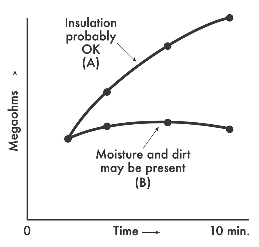
Figure 14: Polarization Index Test
Discharge-Based Insulation Tests
A range of techniques that look at the response of the insulation during its discharge have emerged. These tests all target the polarization behavior of the insulation because, as mentioned earlier in this article, this property is sensitive to moisture in the insulation. Since all three components of current are present during the charging phase of an insulation test, the determination of polarization or absorption current is hampered by the presence of the capacitive and leakage currents. The discharge phase of the test, however, can more rapidly remove these effects, providing the possibility of interpreting the degree of polarization of the insulation and relating this to moisture and other polarization effects.
Isothermal Relaxation Current Test (IRC Test)
This test was developed for testing service-aged medium-voltage cables and grew as a response to problems associated with DC high potential testing of plastic cables. The early installed base of these cables from the 1960s and early 1980s is particularly problematic.
The IRC test uses a 1 kV test voltage for 30 minutes to polarize the dielectric. The polymer polarization traps charge at specific discrete energy levels, and during the discharge process, these energy levels give rise to different time constants in the discharge current. The major use of the effect in the IRC test is to look for the time constant associated with water trees in degraded cross-linked polyethylene (XLPE) cable material. The relaxation current occurring after the capacitance has been discharged is digitized for processing in PC-based software.
The software processing is based on a modelling technique that converts the current into charge and plots this charge against time. The total charge plot is then treated as a composite of standard shapes whose time constants are fitted to the composite curve by iteration. Cable aging is identified by the relative values of the time constants. The test was initially developed using artificially aged cable and has now been applied to operational XLPE cables.
SUMMARY
In Part 1 of our three-part series on acceptance and maintenance testing for medium-voltage electrical power cables, we reviewed cable construction and cable aging characteristics and started our discussion on cable testing options and philosophies. In Part 2 of this article, we will move away from under voltage testing and explore high potential testing techniques.
 Thomas Sandri is Director of Technical Services at Protec Equipment Resources, where his responsibilities include the design and development of learning courses. He has been active in the field of electrical power and telecommunications for over 35 years. During his career, Tom has developed numerous training aids and training courses, has been published in various industry guides, and has conducted seminars domestically and internationally. Thomas supports a wide range of electrical and telecommunication maintenance application disciplines. He has been directly involved with and supported test and measurement applications for over 25 years and is considered an authority in application disciplines including insulation system analysis, medium- and high-voltage cable, and partial discharge analysis, as well as battery and DC systems testing and maintenance. Tom received a BSEE from Thomas Edison University in Trenton, New Jersey.