
Current protection testing practice is the result of history, custom, and seemingly conflicting motivations. Despite dramatic advances in protection system technology, protection testing philosophy and practice have not kept pace. This article reviews past and present protection testing practices and explores ways the industry could evolve to meet current and future challenges.
As it was in the very beginning, the primary objectives of protection testing are to ensure personnel safety, protect equipment, and maximize system availability. At its core, protection testing involves predicting a relay’s intended behavior, providing a test stimulus, measuring the relay’s response, and finally comparing the result to the prediction. Achieving efficient and philosophically sound testing with single-function devices is straightforward. However, as protection systems have grown more complex, industry-standard testing methods have remained essentially unchanged. The effect this has had on the bulk electric system misoperation data, compiled by the North American Electric Reliability Corporation (NERC), is obvious.
A BRIEF HISTORY OF SYSTEM PROTECTION AND PROTECTION TESTING
To understand how current protection testing practices evolved into what they are today, it is helpful to review the history of system protection and protection testing in North America.
The Early Years: Standards Are Established
The concept of modern system protection began around the year 1900 with companies in countries around the world simultaneously developing protection devices for the new electrical distribution system. In North America, competition developed primarily between the Westinghouse Silent Sentinels and General Electric’s protection line would last for 70 years. By the mid-1920s, the development of devices covering the fundamental protective elements we know today was complete. From that point, protection technology development was slow, with only incremental improvements until the 1970s.
The early devices were electromechanical; the testing philosophy was to verify proper operation through cleaning, inspection, exercise, and adjustment. As these devices were electromechanical, they had to be tested while installed in a case to simulate in-service magnetic conditions, leveled to ensure in-service gravitational force on mechanical components, and warmed up to simulate in-service conditions. While under test, these devices were completely isolated from any interposing logic using test paddles or by fully removing the device from the cubicle and installing it into a test case. Installing settings and testing of the device was guided by the device instruction manual and frequently included device-specific tests and a wide variety of mechanical and electrical adjustments.
To verify protection functionality, element pickup and time delay became standard tests. The model used to predict device behavior came from the device instruction manual and incorporated curve characteristics, reach, time delay, and other parameters. As tripping logic was incorporated into the cubicle wiring outside of the device, these tests were conducted separately.
Initially, protection testing was performed using individual, off-the-shelf devices such as variacs, decade boxes, timers, and field-improvised devices. By the 1950s, the first purpose-built protection test equipment combined the previous discrete test instruments in one or more boxes. But even with dedicated tools, protection testing itself required a good understanding of device operation and considerable tribal knowledge to execute.
The 1970s: A First Try for Real Protection System Innovation
The next opportunity for advancement occurred when solid-state protection devices (Figure 1) became commercially viable in the late 1960s. This innovation greatly reduced manufacturing costs and offered high accuracy and operating speed. Packaging ranged from the very compact ABB Circuit Shield to the Basler BE1 line that used electromechanical device cases to facilitate easy changeover to panel-sized line protection cabinets.
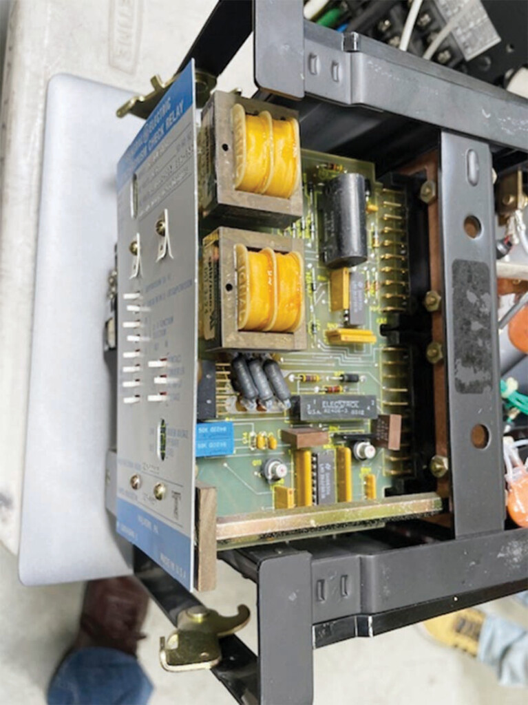
However, limited self-test capability, unreliable failsafe conditions, and the vulnerability of solid-state components and acid-etched circuit boards resulting from substation conditions led to poor reliability. In response, the IEEE Power Systems Relay Committee developed protection device hardware standards such as IEEE Std. C37.90, IEEE Standard for Relays and Relay Systems Associated with Electric Power Apparatus, which proved instrumental in the success of subsequent generations of protection devices.
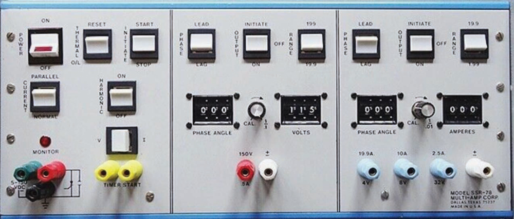
To gain market acceptance, the protective functions of solid-state protection devices were designed to closely mimic the electromechanical devices they were intended to replace. Since discrete solid-state components replaced electromagnetic devices, testing philosophy and techniques remained mostly unchanged. Like the protection devices they tested, Multi-Amp (Figure 2), Jodice Controls, and a few other manufacturers produced relay test sets that took part in the solid-state revolution. These test sets provided substantial innovation in usability but suffered many of the same problems found in the devices they tested.
The 1980s: Digital Devices Appear in the Market
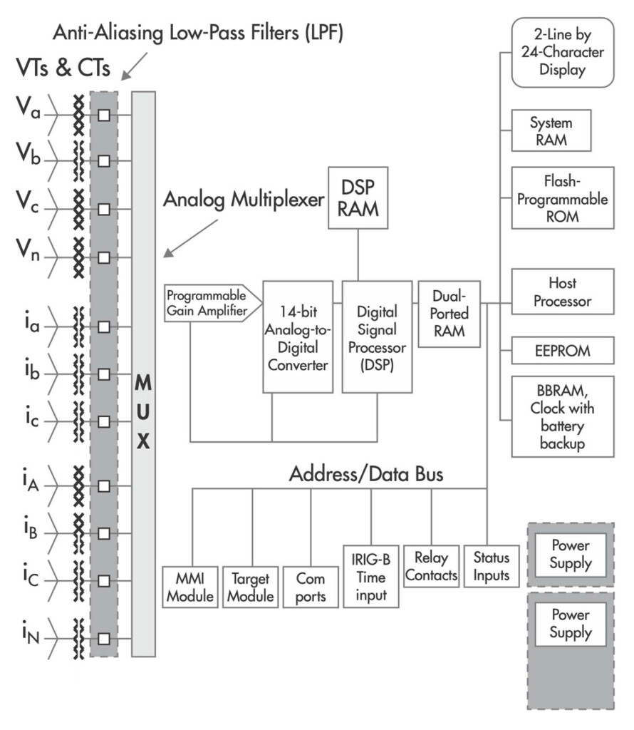
Early devices featured a hybrid architecture with solid-state circuitry for filtering and a microprocessor for performing processing and interfacing with the system and user. Typical devices offered one or two functions. Setting these early digital relays was cumbersome with individual keypad entry of parameters. Like the solid-state relays that preceded them, these early devices were designed to closely duplicate electromechanical relay functionality to gain market acceptance. Later in the decade, fully numerical protection was introduced featuring A/D conversion and fully numerical calculation of operating quantities. While there was serial communication for monitoring and control, settings were entered one at a time with a keypad.
Since these relays duplicated existing electromechanical device functionality and configurable logic was limited and usually fixed, testing philosophy remained unchanged. During commissioning and testing, the new devices needed fewer adjustments, resulting in substantial labor savings. Hybrid digital/electronic protection test sets, such as the Doble F3, saw widespread acceptance. Incorporating solid-state power electronics for power simulation, digital timers, and more efficient user interfaces, these devices greatly simplified protection testing.
The 1990s: The Digital Revolution Gains a Firm Foothold
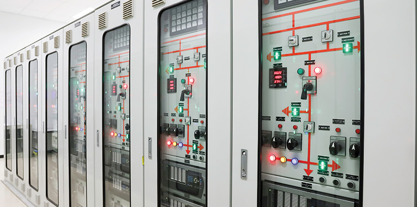
As the lower cost, smaller footprint, reporting advantages, easier maintenance, and near-term reliability of digital devices became irresistible, digital relays were widely accepted. Common features of this vintage included extensive power-up and running diagnostics and a serial computer interface for parameterization via personal computer. The concept of protection and control was introduced. Programmable logic was commonly used, facilitating more complex supervisory and communication-assisted schemes while minimizing interconnecting wiring. Toward the end of the decade, drawout cases were fully abandoned in favor of 19 rack-mounted devices, further driving prices down. Regardless of the possibilities, market positioning concerning protective element functionality remained conservative, and protective function algorithms still closely mirrored the operation of previous generations of protection devices (Figure 3).
On the testing side, regardless of the dramatic change in how protection devices worked and failed, traditional pickup and time-delay testing persisted. In other areas, some important changes took place.
Advances in digital technology and solid-state power electronics facilitated the introduction of a new generation of test sets. Earlier test set models, such as the Doble 2253, Manta MTS-1710, and Multi-Amp Pulsar, were semi-portable and were controlled via the front panel. Later in the decade, further advances in power electronics and the proliferation of portable computers facilitated truly portable, computer-controlled test sets such as the Doble 6150, OMICRON CMC, and others. Rudimentary test macros, test plans, and automated test reporting made testing more efficient.
As fully digital protection devices contained multiple protective functions and programmable trip equations, isolating a function for accurate pickup and time delay testing was difficult. For the first time, changing relay settings during testing became common practice, with obvious philosophical shortcomings. This resulted in numerous as-left errors, and improper settings, logic, and design rose to the number one cause of misoperations.
The 2000s: Digital Devices Dominate the Market
The 2003 Northeast Blackout brought significant changes to the protection testing industry. In the aftermath of the blackout, the lack of detailed fault data was a driver for more digitization of protection and control. Although primarily caused by poor vegetation management and operational errors, existing system protection practices exacerbated the event, causing the Federal Energy Regulatory Commission (FERC) to act. In response, NERC PRC-005 became enforceable in 2007, and for the first time, operators of the North American bulk electric system had to carefully organize and document their protection maintenance practices to avoid substantial fines. The influence of numerous post-deregulation mergers and acquisitions naturally led to an intense desire to harmonize protection and control products, practices, and data across the various entities within modern utilities.
Elsewhere in the industry, innovation in digital protection continued:
- Rudimentary programmable logic introduced in the 1990s was continuously expanded to include substation automation functionality. Programmable front-panel buttons that expanded device capability and further reduced interconnecting wiring for logic and control functions were widely offered.
- Peer-to-peer communication schemes featuring fiber communication became commonplace.
- As device settings became more complex, the potential for errors increased. In NERC-published reports on misoperations within the bulk electric system, “setting, logic, and design” errors surpassed hardware errors to become the leading cause of reportable misoperations (Figure 4).
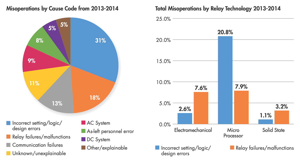
Source: National Electrical Reliability Council 2013–2014 NERC Misoperation Report
For protection testing, regulatory compliance and lack of human resources emerged as pain points, driving an intense desire to automate and streamline protection testing practices. GPS-synchronized end-to-end testing became routine at many utilities, and more sophisticated test set control software that allowed for more realistic simulations became widely available. Test set hardware continued to evolve, offering additional analog and binary channels for more complete simulations. Although more realistic testing was adopted, the industry still routinely changed settings to facilitate function pickup and time-delay tests. Due to the drive for uniformity and regulatory compliance, concentrated testing on settings, logic, and design remained a secondary effort.
The Present: Accelerating Change in Protection, Control, and Automation
Ever-increasing computing power is facilitating rapid evolution in protection technology. While traditional protective functions are still the standard, the industry is now open to expanding existing definitions and creating new ones altogether. One example is adapting transformer current differential slope behavior. This algorithm anticipates current transformer saturation conditions and adjusts the operating slope based on pre-fault current conditions. While it is possible to test with traditional function-based testing methods, this algorithm will require workarounds.
Another example of a new — or at least new to the market — algorithm is functionality that operates in the time domain. Unlike traditional phasor-based algorithms, these functions operate in entirely new ways. Incremental quantity distance elements rely on precise and realistic transitions from the pre-fault to the fault state. Traveling wave protection and fault location also operate in the time domain and cannot be tested with traditional methods.
The Future
As the interest in peer-to-peer communication between protection system components increases, IEC 61850 will likely become mainstream. Taking this a step further, with merging units mounted at the substation apparatus supplying sampled values, there will be little need for protection devices with analog input channels. Therefore, discrete protection devices will likely lose market share in favor of rack-mounted computers providing all protection, automation, and control functions. Protection functionality will no longer be constrained to traditional protective function definitions, but instead be constructed as needed.
TESTING METHODS COMPARED
With the entire protection system installed in one device using inputs from sources around the station, testing using function-based methods will simply no longer be possible. Substation testing will have to be accomplished using system-based testing.
Function-Based Testing
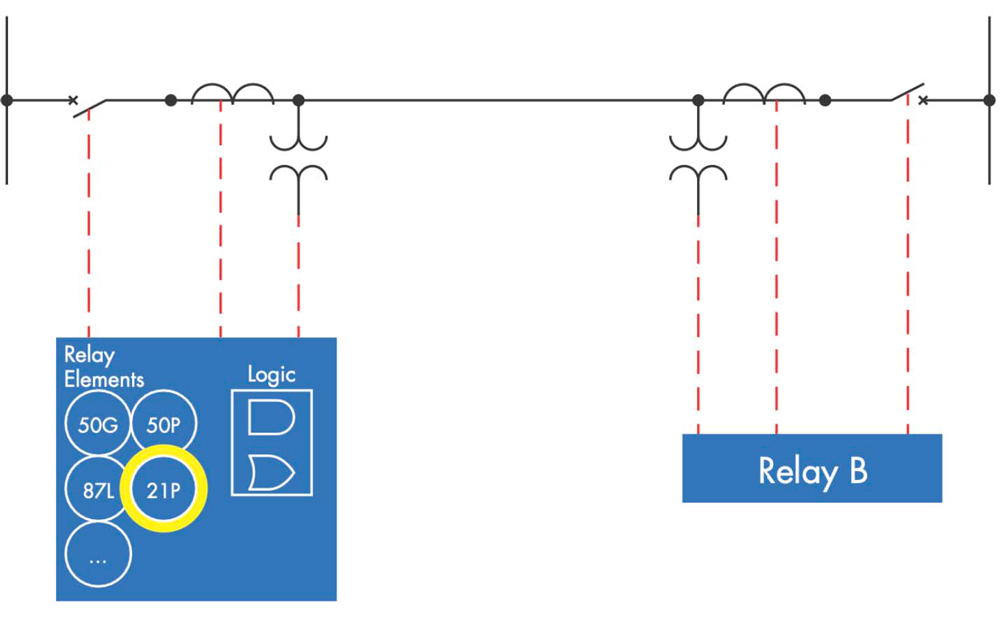
During traditional function-based protection testing (Figure 5), the device under test is modeled to predict the behavior of the device: tap, curve, time dial. One or more test points are then selected based on the test objectives, test set capability, and organizational requirements. The test set is then used to measure relay response at each test point. This type of testing can be performed manually or automatically using test set control software with varying degrees of automation based on software capability or operator preference.
With this method, the test software protection model must be compatible with the protection function algorithm in the device to be tested. Until recently, this has presented few problems, as protection devices closely followed historical protection device functions. However, as new devices are no longer bound to the old function definitions, this will not be the case in the future.
During function-based testing, testing effort varies with the complexity of the device under test. This method is very straightforward on single-function devices with no programmable logic such as electromechanical devices. However, modern protection devices typically have many potentially overlapping protective functions, making it difficult to perform pickup and time-delay tests without inadvertently operating other elements enabled within the device. To overcome this, test settings can be carefully selected to avoid overlapping elements. However, common industry practice today is still to isolate the element under test by manipulating the protection device settings — and likely bypassing any programmed logic in the process. This practice minimizes the possibility of identifying logic errors in the settings.
The effectiveness of function-based testing also depends on the data source for the test model. If the test model is derived directly from the device settings, it is impossible to identify setting or design errors. Without advanced software, mathematically expedient test stimuli are frequently employed. This can result in unanticipated results in devices employing advanced algorithms to operate or supervise protective elements.
Limitations to test software and hardware can also result in waveform discontinuities. Examples of this are resetting phasor diagrams at state changes or stepping parameters instead of smooth ramping. This can result in unanticipated results with functions such as rate of frequency change, devices using sophisticated measurement, or supervision algorithms such as incremental quantity distance elements.
Despite the substantial shortcomings of function-based testing, there are benefits such as industry familiarity and existing integration in regulatory compliance and workflow automation programs.
System-Based Testing
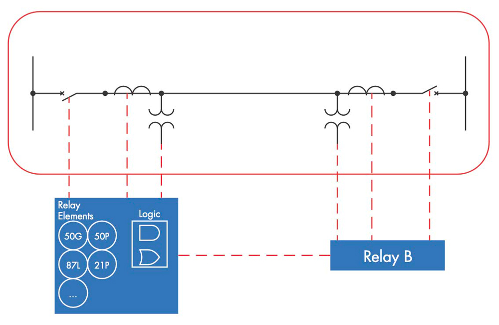
Instead of modeling the device under test, system-based testing (Figure 6) models the associated power system. Once the system model is created, tests are carried out with a series of test scenarios such as faults in various locations or system events such as breaker failure, power swing, or system voltage transients.
System-based testing is not new. Long ago, thin wires were shot over transmission lines to verify proper system operation. Now, system-modeling software such as Aspen, CAPE, and others give us a much better solution by isolating a bus and creating SS1 or COMTRADE event files for faults modeled in various locations. Digital relays now give us another source for realistic transient files. These files can be played back with any modern test set to evaluate specific power system scenarios. More recently, system-modeling software has become available to test engineers in the field.
This approach has several advantages:
- Unlike protection device technology, power system behavior remains stable over time. A realistic test scenario will work with any protection device, regardless of manufacturer or model.
- As settings are not manipulated during the test, setting, logic, and design errors are more easily detected with realistic simulation of system events.
- More detailed results can be obtained, such as measuring the effects of CT saturation or how sensitive the existing protection scheme is to faults near the neutral connection in a transformer.
- Complex scenarios such as evolving faults, parallel line scenarios, three-terminal lines, autotransformers, and system operations such as reclosing can be easily tested.
- The test stimulus and the protection system response can be more easily visualized. This leads to better test quality and reduced testing effort for complex schemes.
To perform a test, the system is first modeled. The extent of the model is determined by the testing scenarios desired and can include a single apparatus like a transformer or line, an entire substation, or a complex system of lines. The part of the system left unmodeled is represented by a source impedance and angle at each interconnection. Next, physical, or virtual test set channels required for the test are mapped to points on the protection devices in the system model. Finally, test scenarios are created to test the desired protection functionality. Each scenario is then executed, and the relay response is measured and reported.
Comparing the effectiveness of the two methods in detecting the reported causes of reportable misoperations on modern devices illustrates a stark difference (Figure 7).
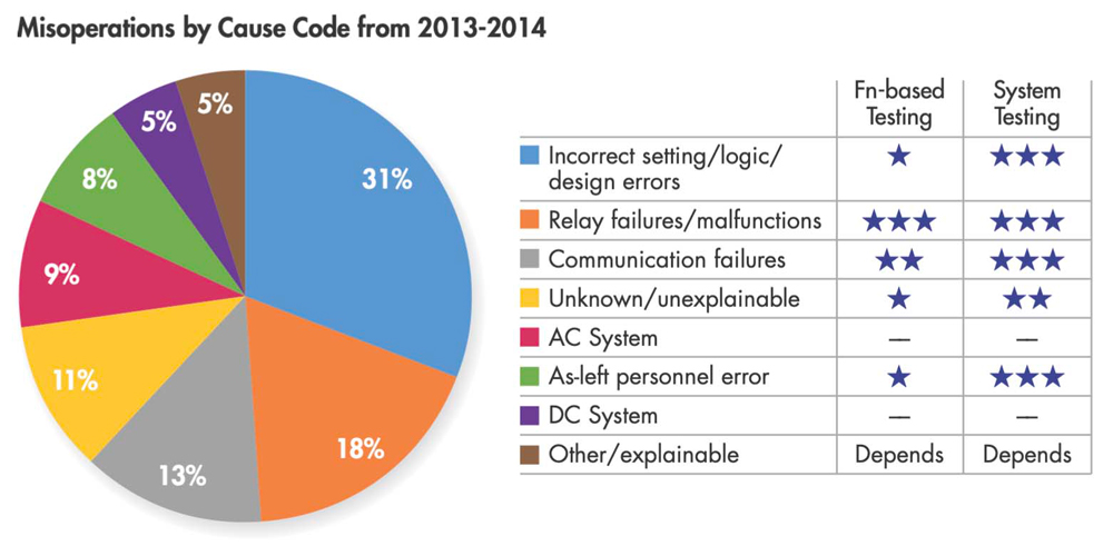
Source: National Electrical Reliability Council 2013–2014 NERC Misoperation Report
CONCLUSION
While the primary purposes of protection testing remain constant, test methods must advance to continue to meet objectives as the protection system evolves. System-based testing provides a reasonable, effective, and future-resistant solution to the challenges ahead.
REFERENCES
[1] Lindqvist, Bertil. 100 Years of Relay Protection, the Swedish ABB Relay History, ABB Automation Products, Substation Automation Division. Accessed at https://library.e.abb.com/public/c1256d32004634bac1256e19006fd705/PAPER_2001_08_en_100_Years_of_Relay_Protection__the_Swedish_ABB_Relay_History.pdf. [2] Sticht, Christopher. NERC Misops, Oak Ridge National Laboratory, December 2021. Accessed at (https://www.osti.gov/servlets/purl/1836418). [3] Westinghouse Electric and Manufacturing Company. Silent Sentinels, Protective Relays for AC and DC Systems, 1928, Updated December 2022. Accessed at https://archive.org/details/silentsentinels_2212_librivox. [4] National Electrical Reliability Council. 2013-2014 NERC Misoperation Report, May 2015. Accessed at https://www.nerc.com/pa/RAPA/PA/Performance%20Analysis%20DL/2015%20State%20of%20Reliability.pdf.
Scott Cooper is the Application and Training Engineer for OMICRON in St. Petersburg, Florida. He has thirty years of experience in a variety of roles including substation commissioning, application engineering, power plant operations, and technical training. He is active in the IEEE PSRC and has written numerous papers and magazine articles. Scott is a graduate of the United States Navy Nuclear Propulsion program.