

An electric arc or arc flash occurs when a high voltage causes ionization of a gas — for example, air. Ionization turns an ordinarily nonconductive gas into conductive gas that can carry a sustained current. The color of a typical arc flash in air is very distinctive. This is because air is composed of 21% oxygen and 78% nitrogen; oxygen plasma glows blue, and nitrogen plasma glows purple,[1] thus producing the familiar purple-blue arc-flash color. Different gas plasmas will yield different colors; for example, an arc in neon gas produces an orange glow, while an arc in sodium produces a hint of yellow as seen in streetlights.
An electric spark is distinct from an electric arc. An electric spark is only momentary, while an electric arc is sustained. A controlled electric arc has many practical applications due to its high brightness and high temperature output. Examples include the carbon arc search lamp used at night, arc welding, and the Xenon arc bulb used in IMAX projectors.[2] However, the electric arc’s high brightness and high temperature can make it very dangerous when it occurs in an uncontrolled manner.
In the movies, an electric arc might cause Arnold to appear in the middle of the night or the passenger in a Delorean to be sent back in time, but in real life, an uncontrolled electric arc can cause severe personnel injury or death, destroy switchgear, and cause prolonged unplanned outages. Between 1984 and 2007, there were 85 recorded deaths due to arc flashes.[3] With suitable equipment options and arc-flash detection methods, modern advanced high-speed digital relays can save lives, reduce personnel injury, prevent and reduce property damage, and avoid unplanned outages more effectively than ever before.
ARC-FLASH DETECTION METHODS
A robust arc-flash detection (AFD) and protection system should perform well in the categories of speed, dependability, security, sensitivity, selectivity, and availability. Fast detection and clearing of an arc-flash event minimizes incident energy,[4] thus reducing damage to equipment and personnel. Existing AFD systems have used sound, pressure, current, light, ion detection, thermal imaging, and a combination of these methods to detect arc flashes.[5]
Although an electric arc contains powerful sound and pressure waves, it is most effective to use light as the primary arc-detection medium. Light is easier to simulate and assists users in testing the arc-flash element operation during commissioning. However, the light-only detection system poses security risks that an intense light source, other than an arc flash, will initiate a trip; this includes light sources such as a camera flash, laser, floodlight, or bright sunlight. All of these items can produce light intensity exceeding the arc-flash detection level.
An arc-flash event is typically associated with moderate to very-high fault current levels. Conventional instantaneous overcurrent elements can protect equipment, but lack sensitivity, selectivity, and speed to prevent or minimize personnel injury during an arc-flash event. The challenge with an instantaneous overcurrent detection system is selecting proper trip settings. The settings must be high enough to account for variation in load current, yet low enough to detect a fault event quickly. Lack of selectivity causes the element to detect faults outside the protection zone. Therefore, coordination with downstream protection devices is required, thereby slowing the element down. Thus, an overcurrent-only detection system is unsuitable for AFD applications.
Combining the merits of light- and current-based schemes results in an AFD protection system that is reliable and superior in various performance categories. Figure 1 shows an AFD protection system in medium-voltage switchgear that uses both light and current. This scheme uses a high-speed light element in combination with a fast overcurrent element to produce a trip output. The digital relays 1, 2, and 3 measure current using the corresponding current transformers (CTs). Light is measured using corresponding point or bare fiber loop sensors. Sensors are located such that the AFD would trip the corresponding upstream circuit breaker. Temporary activation of the current supervision overcurrent element during inrush, load pickup, or external fault conditions is expected. However, this overcurrent condition will not cause an undesired trip because an AFD trip requires both light AND current.
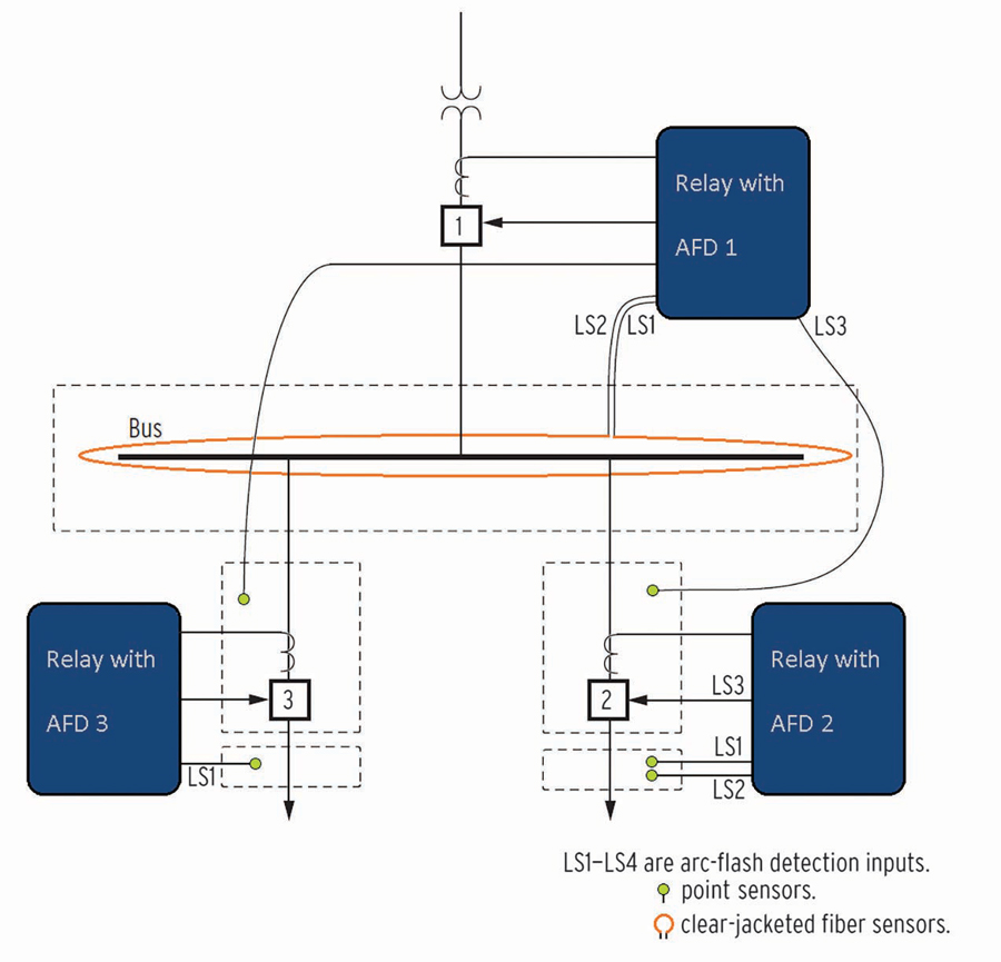
Figure 1: Arc-Flash Detection Switchgear Application[6]
The point sensor consists of a jacketed fiberoptic cable terminating on a small collector lens (Figure 2). It is directional and can detect light in a specific area.
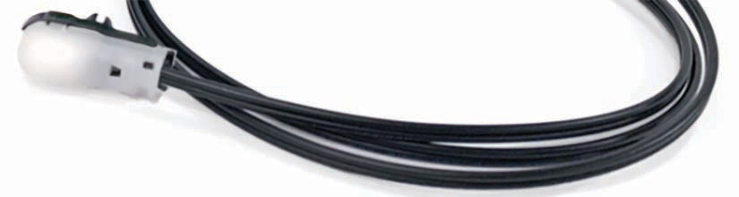
Figure 2: Arc-Flash Point Sensor
The bare loop sensor consists of high-quality fiberoptic cable without a jacket (Figure 3). Fiber loop sensors can provide coverage over open areas in the switchgear cubicle.
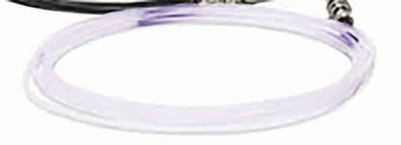
Figure 3: Arc-Flash Bare Fiber Loop Sensor
AFD system manufacturers provide general guidance on sensor location and routing considerations inside the cubicle. Strategically mounting sensors where arc-flash incidents are most likely to occur enables fast detection and hazard mitigation. Arc-flash incidents are the most common in areas of transition between conductor types. Examples of increased arc-flash risk locations are incoming line sections where the changes are from wire to bus, breaker stab points, and bus section transitions. Consider the following precautions while routing fiber cables and point sensors:[7]
- Use caution when installing the fiber by maintaining a large bend radius, at least two inches (five centimeters), and minimizing contact with sharp edges.
- Scratches and gouges of the outer wall of the bare fiber can significantly decrease light sensibility. Use caution while pulling the bare fiber through the ties or wire looms.
- Mounting should stay clear of any conductors, pinch points, or mechanical interferences.
Sampling rate, digital filtering, and the processing rate of light and overcurrent elements impact the speed of arc-flash detection. One of the challenges of using current supervision is to ensure that the current detection is as fast as the light detection. The fast overcurrent element using raw samples can operate in approximately 1 millisecond for arc-flash events. Conventional instantaneous overcurrent elements that operate on filtered fundamental current can take 8–20 milliseconds and are therefore too slow. In addition, standard electromechanical output contacts can delay operating time by as much as 8 milliseconds. Using fast hybrid (solid-state) contacts for tripping can reduce this delay to 50 microseconds.[6]
Manufacturers can also implement additional logic to enhance light-detection performance, for example, by including a time-overlight® (TOL) algorithm for light detection. Figure 4 shows inverse curve characteristics used by the TOL pickup element. The TOL characteristic offers faster trip times for higher levels of light and a guaranteed minimum trip time when the light is just above the pickup. This algorithm can also provide security in detecting light by confirming multiple light samples before issuing a trip. Newer relays with faster processors will perform even faster.
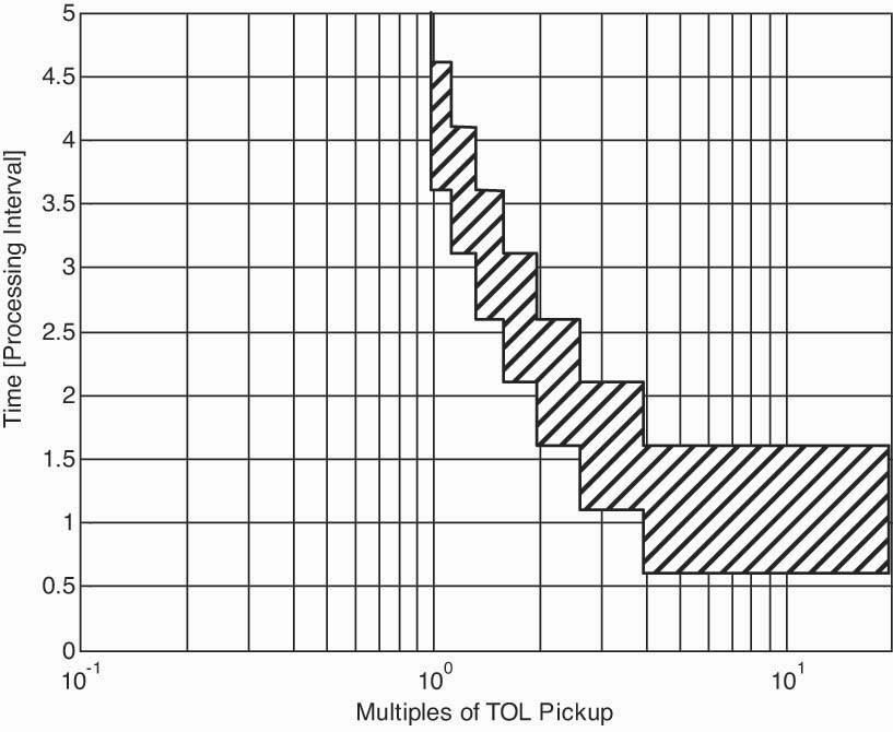
Figure 4: TOL Element Inverse Curve Characteristic[6]
Reliable arc-flash detection and circuit isolation also depend on the health of the protection relay, light sensors, circuit breaker, and control circuit. It is equally important that these devices are maintained and ready to operate. Substation battery monitoring and trip coil monitoring functions can be enabled to alert the operator to issues with the control circuit and circuit breaker.
Self-diagnostics can add an additional layer of reliability by periodically testing the continuity of the fiberoptic arc-flash sensors. The diagnostics enable the digital relay to monitor the health of the fiberoptic cables and promptly detect damage that renders the fiberoptic cables ineffective. It should be made clear that the diagnostic warning itself does not correct the issue. The warning only provides notification that the arc-flash protection may be compromised due to a damaged arc-flash sensor.
EVENT REPORTING
An advanced AFD system offers a metering option to allow the user to measure the ambient light and set the light-sensing element appropriately during commissioning. The light metering feature is a valuable tool to check changes to ambient light for periodic maintenance.
Modern digital intelligent electronic devices provide event reports to analyze the cause of relay operations. These reports record digital and analog data, including light and current levels, from the time of the event and help in analyzing the element operation.
On June 4, 2014, an arc-flash event occurred in a 6.6 kV switchboard cubicle. A dead mouse was found near the cable termination (Figure 5).
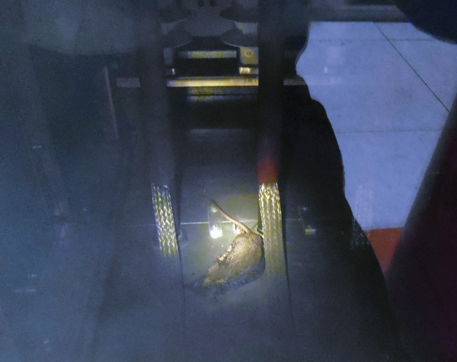
Figure 5: A mouse caused the arc flash.
Figure 6 shows the oscillography generated by the relay. IA, IB, and IC are the current channels for the three phases, and LSENS1 is the light intensity measured by light sensor 1. The output contact in the relay operated on the arc-flash light sensor input, which was supervised with the current input. Note that the high fault current caused the analog-to-digital converter to clip. Because of the fast arc-flash detection algorithms of the AFD, the feeder relay detected and operated for the fault in 1.25 milliseconds. The operate time includes the operation of the solid-state output contacts of the AFD relay. The circuit breaker operated and cleared the fault in 2.25 cycles of the power system frequency. The relay’s fast detection and circuit isolation confined the damage to one feeder; the remaining feeders on the switchboard were unaffected.
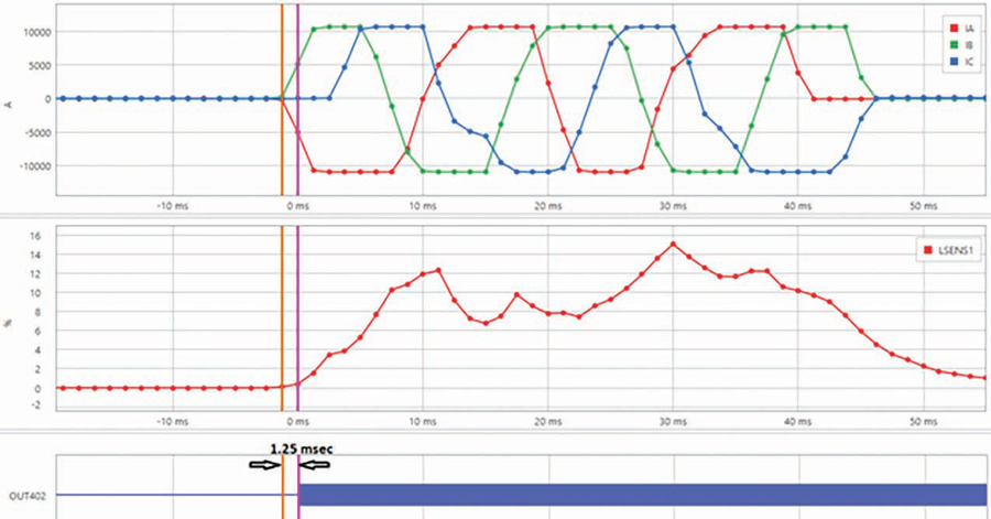
Figure 6: Arc-Flash Event Waveform
Figure 7 shows the oscilloscope capture of the arc-flash element testing. The testing results indicate element operation as fast as 1 millisecond. A light input (yellow-colored trace) and current input (green-colored trace) were simultaneously applied to the relay. The magenta-colored trace indicates the solid-state output contact closing based on light, and the cyan-colored trace shows the hybrid output contact closing based on the current. The element operated in 966 microseconds.
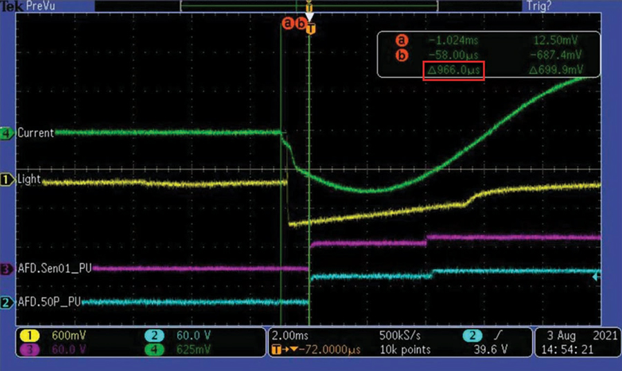
Figure 7: Oscilloscope Capture of the Arc-Flash Element
CONCLUSION
Fast detection and clearing of an arc-flash event minimizes incident energy,[4] thus reducing damage to the equipment and personnel. A robust arc-flash protection system should perform well in the categories of speed, security, dependability, sensitivity, selectivity, and availability. Use of both light and current allows operators to combine the merits of both methods, resulting in an AFD protection system that is reliable and superior in various performance categories.
REFERENCES
[1] H. Pniok. “Periodensystem der Chemischen Elemente Das Periodensystem der Chemischen Elemente in Bildern,” Available: pse-mendelejew.de/en.
[2] Museum of Electric Lamp Technology. “Osram-Stud Short Arc Xenon XBO1001,” lamptech.co.uk. Available: lamptech.co.uk/Spec%20Sheets/D%20G%20Xe%20Osram%20XBO1001.htm.
[3] M. C. Wellman. “OSHA Arc-Flash Injury Data Analysis,” 9 March 2012. Available: ieeexplore.ieee.org/document/6165547.
[4] G. Rocha, E. Zanirato, F. Ayello, and R. Taninaga. “Arc-Flash Protection for Low- and Medium-Voltage Panels,” proceedings of the 58th Annual Petroleum and Chemical Industry Technical COnference, Toronto, Canada, 2011. Available: selinc.com/api/download/114443.
[5] R. J. Burns, A. D. Baker, and D. E. Hrncir. “Strategies for Reliable Arc Flash Detection in Low-Voltage Switchgear,” 2018. Available: eaton.com/content/dam/eaton/products/low-voltage-power-distribution-controls-systems/switchgear/low-voltage-switchgear-documents/strategies-for-reliable-arc-flash-detection-in-low-voltage-switchgear-wp019004en.pdf.
[6] Schweitzer Engineering Laboratories. “SEL-751 Feeder Protection Relay Instruction Manual,” 2021. Available: selinc.com/api/download/10737/?lang=en.
[7] M. Zeller, A. Hargrave, and D. Haas. “Using the SEL-751 and SEL-751A for Arc-Flash Detection,” SEL Application Guide (AG2011-11), 2011. Available: selinc.com/api/download/9593/?lang=en.
 Hang Li is a Lead Power Engineer at Schweitzer Engineering Laboratories, Inc. He has been working at SEL since 2014. He earned a BSEE from Washington State University and an MSE from the University of Idaho.

Deepti Almelkar is the Product Engineer at Schweitzer Engineering Laboratories, Inc., where she is responsible for product development and support for industrial platform protection relays. She has worked in the industry for more than nine years with responsibility for substation engineering design and power system protection. Deepti graduated from Mumbai University, India, with a BS in electrical engineering. She earned an MS in electrical engineering specializing in power systems from North Carolina State University.