

With an ever-growing demand for a more reliable distribution grid, utilities are constantly looking for possibilities to optimize their distribution networks by implementing distribution automation. One method to improve the network and reduce permanent outages is using pole-mounted reclosers, due to their wide range of functionality. By introducing built-in voltage sensing on both source and load sides, automation can easily be achieved by using local, built-in logic to isolate a faulted section and closing in a tie recloser to supply power to customers from an alternate source.
Automation schemes utilizing coordinated protection functions provide an easy and low-cost solution to improve reliability. However, the process of isolation and service restoration can take up to several minutes. For critical feeder lines where long, temporary outages are unacceptable, reclosers equipped with high-speed peer-to-peer communication provide possibilities to locate, isolate, and restore power to unfaulted sections within seconds or faster. With the American Recover and Reinvestment Act of 2009 providing $4.5 billion to the U.S. Department of Energy to modernize the electric power grid, most of the funded SmartGrid projects include communication-assisted distribution automation.
To put such projects into operation, utilities often rely on manufacturers to design and implement the automation scheme. Thorough testing of the entire scheme prior to installation is critical to ensure that the switching logic works as desired for the multitude of fault scenarios that may affect the network and verify that the communication equipment can support the resulting network traffic. The testing process is integral for the verification of the system, but can also be extremely complex, labor intensive, and time-consuming. This article suggests an easy-to-apply method to test any distribution automation network that can significantly reduce testing time. At the same time, it covers parameters that can verify correct operation of distributed automation schemes, which are typically not included in routine conventional testing.
Feeder Automation Configuration Example
There are many ways to automate feeders using reclosers. One commonly used method is to connect two feeders at an interconnection point (R5) using a normally open recloser (Figure 1). While the number of reclosers used in the scheme may vary, this example provides a general idea of the concept.
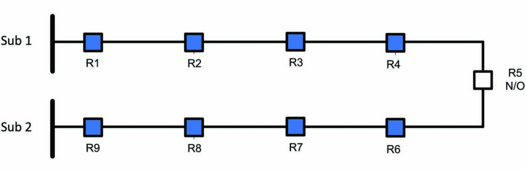
Figure 1: Typical Feeder Automation Example with a Tie Recloser
If a fault occurs (Figure 2), R3 must trip first to interrupt current flowing into the fault. To isolate the faulted section, R4 should open next. The feeder supplied by Sub 2 should then be checked to verify that it can supply the additional load between R4 and R5. If the load can be supplied, the normally open R5 will close, restoring power to customers who would otherwise be left out of service.
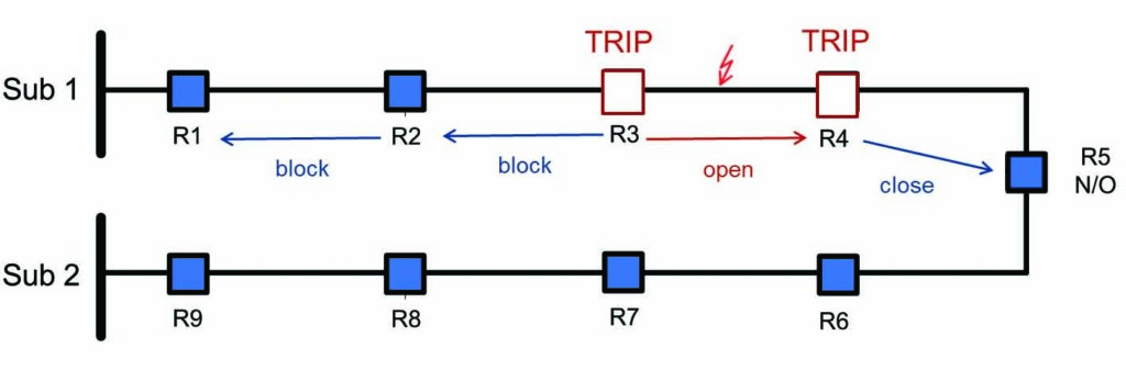
Figure 2: Fault Location, Isolation, and Service Restoration in Case of a Fault
Now that power is restored to customers between R4 and R5, R3 will try to reclose to verify whether the fault was only of a temporary nature.
Achieving this type of functionality can be done in a variety of ways. The simplest method is to rely only on local logic in each recloser; this logic is based on a voltage function. In case of a permanent fault, recloser R3 will typically try to reclose until lockout. Meanwhile, a timer in R4 will initiate after it detects a permanent loss of voltage and eventually open after a set amount of time based on protection settings. Since R5 has lost voltage on one side, an undervoltage timer will start to count and will close after a defined time.
Purely based on voltage logic, this scheme will typically take a minute or more to restore power to non-faulted sections, which may not be acceptable for critical feeder lines. This isolation and reconfiguration process can be significantly improved by using communication to or between the reclosers in the field. In case of a fault, the recloser could then quickly send an open or closing signal to downstream and tie reclosers.
Communication Platforms and Performance
The automation scheme’s performance greatly depends on the communication platform. A wired network using fiber-optic cables is one of the fastest solutions available, since it offers high bandwidth and low latency. However, implementing schemes with new fiber-optic networks can be very expensive, and considerations must be made for the number of protection devices and the distances between protection devices. An alternative solution is to use wireless networks, which can be easily established and expanded and can fulfill both bandwidth and latency requirements. Utilities often have a choice to use public or private wireless networks. When deciding whether to implement a public or a private network for communication, a number of factors must be considered. Cost certainly is one factor, but service availability and coverage are also very important. Aside from the communication platform, the performance of the scheme also depends on the number of connected devices, the communication distance, and certainly the communication technology.
Testing Protection Functions
If the scheme’s protection is not based on communication or distributed logic, testing the protective functions of the recloser control can be performed with minimal effort via secondary injection testing for individual recloser controls. Some test sets can be universally connected to the control cable interface of any recloser control with short recloser-specific adapters. Some simulate the recloser with up to six voltages and enable three-phase testing of the controller in both lab and field environments.
Testing Distribution Automation Schemes
Testing a distribution scheme with communication and distributed logic verifies the correct functionality of all protection devices in the scheme. A distribution automation scheme can be implemented with hundreds of lines of custom logic code in the recloser control and/or a programmable automation controller. Before a scheme is deployed in the field, it should be thoroughly tested to ensure that the scheme operates as expected, especially once it is put into operation. When a fault occurs, the distribution automation scheme must identify the location of the fault, determine the best way to clear the fault, and restore the unfaulted line segments through various switching sequences. These switching sequences must also be tested to fully verify the functionality of the scheme.
Typical Scheme Tests in a Lab
To test a distribution automation scheme in a lab, all devices are set up in a test environment. These tests are typically performed as a proof of concept for new projects or for acceptance testing a scheme prior to installation in the field. Using secondary injection test devices connected to each recloser control, various pre-programmed test sequences can be executed to test the logic and the communication, which are essential to the scheme (Figure 3).
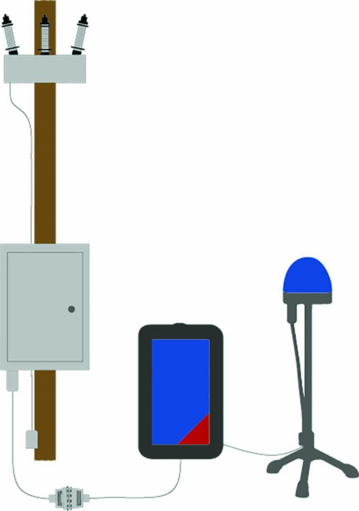
Figure 3: Secondary Injection Test Device Connected to Recloser Control
Scheme testing can be complex (Figure 4), and may require weeks to complete. To simulate realistic faults in every fault scenario, load and fault values for each operating state must be calculated for every recloser in the scheme. To execute each test case, vocal coordination to turn injection from each test device on and off at designated times to simulate each step of the test case is required. Any mistakes or mis-coordination among test personnel would result in an inaccurate test. After execution, results from each location must be collected, merged, and assessed. If any issues are discovered, the automation logic must be adapted to address the problems.
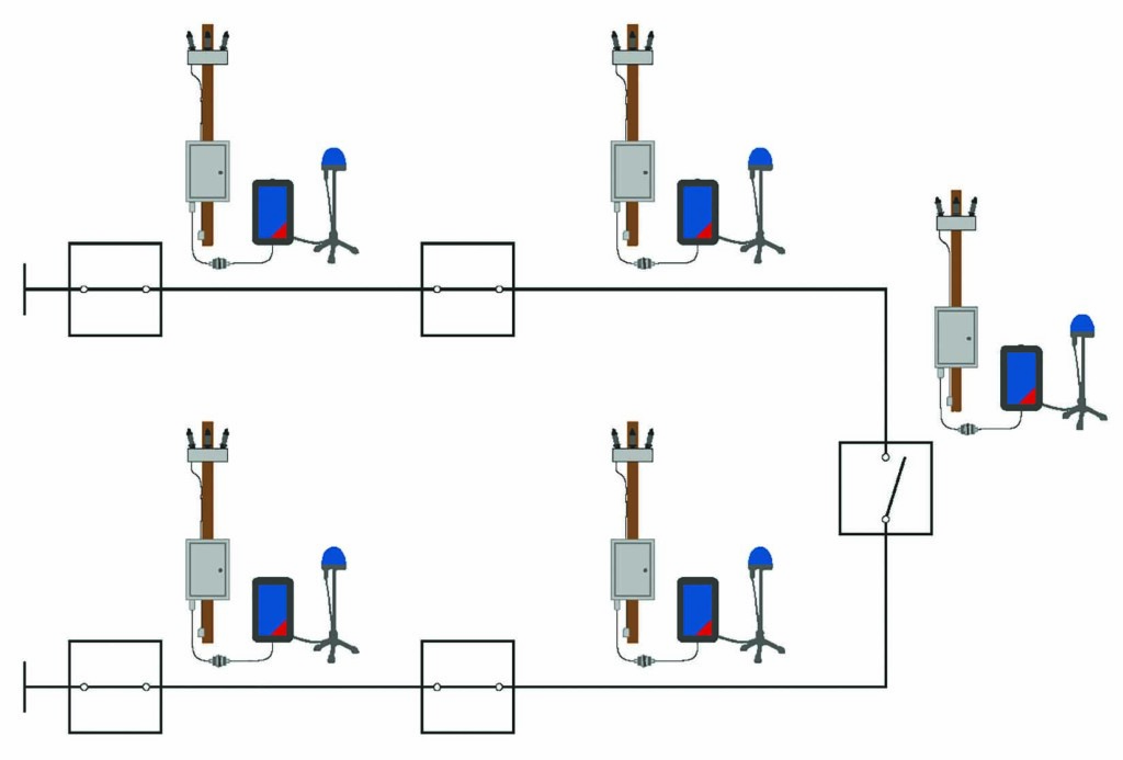
Figure 4: Typical Lab Setup
To synchronously test a scheme involving several reclosers, a single test device can be assigned for each recloser location, which then requires synchronization (e.g., via a GPS or IRIG-B signal).
Shortcomings of a Typical Lab Test
This method has proven to work well for lab testing. However, it comes with several disadvantages: The expected test values have to be calculated and programmed into a sequence for every single test device — a very time-consuming process. After running the test, additional time must be spent comparing the time stamps of each test result from each different testing device. All this effort can represent additional complications.
Two factors that can influence the performance or even the basic function of the scheme must also be considered. When distribution automation schemes are installed in the field, distances between the individual reclosers can be much farther than when testing in a lab environment. Longer communication distances with possibly weak communication links and waveforms of faults that are different from static fault values can drastically affect the operation and testing of the scheme.
Influence of Communication Equipment
Communication equipment used in automated high-speed distribution automation schemes is a critical component. The performance of the scheme greatly depends on the selected communication media, which defines how fast and how much information can be transmitted from one device to another. Only certain technologies provide enough bandwidth, security, and reliability to transmit wirelessly (e.g., an IEC 61850 GOOSE message). Other commonly used wireless transmitting technologies include WiMAX, LTE or 4G.
Transmitting and receiving functions can be affected by greater distances in field installations. In the case of a weak link or overflow on the communication channels, the automated scheme might fail. For this reason, synchronized injection testing into all devices in the field is recommended to test the scheme under real-life conditions.
Transient Waveforms
A test under real-life conditions requires the test values to match those of a real fault as closely as possible. With conventional testing methods, static fault values are typically applied, and the resulting reaction from the recloser control is measured. Under realistic fault conditions, a dc offset is present, and depending on the algorithms of the recloser control, one device in the scheme might detect the fault faster than another. To determine the real performance of the scheme, it is beneficial to test with transient signals.
New Approach for Scheme Testing in the Field
Using new software solutions, distribution automation schemes can be tested in the lab or the field while remotely controlled from a single PC. In addition to addressing the issues described previously, this greatly reduces the testing time while providing comprehensive reporting and troubleshooting options.
A power system under test can be modeled in a single-line diagram editor (Figure 5), and devices such as reclosers and circuit breakers can be placed in the network. Infeeds are defined by entering the source-impedance-ratio (SIR), the line data calculated by using line length and impedance, and loads in the network specified using active and reactive power data. Using this information, the software can calculate the resulting load and fault values for any user defined test case.
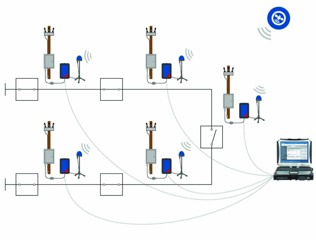
Figure 5: Power System Model Using Software
The behavior of circuit breakers and/or reclosers should be defined within the simulation software. If the circuit breaker and/or recloser opening and closing times are known or have been previously measured using a breaker timing test device, the software allows the input of those times, which are taken into consideration to ensure a more realistic test. Secondary injection test devices have a built-in circuit breaker simulator, which can be extremely beneficial for testing purposes. Using the binary outputs of the test device, the 52a and 52b contacts can be simulated without requiring the circuit breaker or recloser to be connected during the test.
For a lab or field test, a single test set must be connected to each recloser control or relay to inject the appropriate current and voltage inputs and binary inputs (52a/b), as well as receive the resulting binary outputs (trip/close commands). However, when performing a field test, protection points can be located several miles from each other. The system must use either an existing communication network or an external cloud service with remote connection. In this case, all testing devices must be synchronized to GPS for time-synchronized injection (Figure 6).
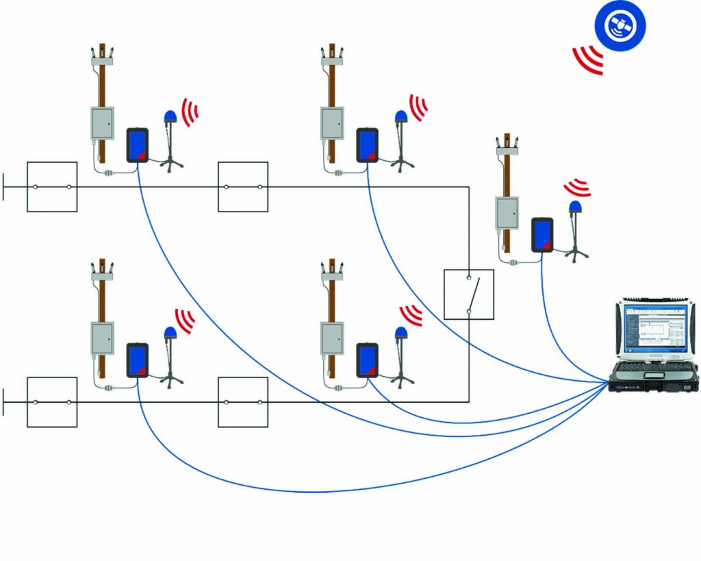
Figure 6: Typical Setup for GPS Time-Synchronized Transient Simulation Test of Recloser Controllers Using a Test Device at Each Protection Point
Once GPS synchronization is established, test devices in the scheme can communicate with each other, as well as with the associated PC running the simulation software over the network. The PC must have access to the network to establish communication with all the test devices. Individual GPS antennas are used to synchronize all test devices at each protection point.
For each test case, a fault can be defined within the single-line diagram of the scheme; the software then calculates the resulting fault values for each device at each location. When the test is executed, the software sends the calculated test values into all test sets. Once all the test values at the test devices have been received, the injection begins synchronously.
A closed-loop test would be ideal; after a device issues a close or open command, the software would calculate new values taking into account the changed values after, for example, a breaker opening. This is not possible with a distributed test. When this mode is enabled, the software runs the first test; once a device under test in the scheme reacts, the software recalculates the test values taking this operation into account. It is assumed that a device under test will always react in the same time if the same test values are applied.
After resetting the scheme, the test is then repeated as the second iteration. The software automatically repeats the calculations after each iteration, taking all breaker and recloser operations into account. This iterative process will continue to reset and run until the system under test no longer reacts. This is typically the case once the fault is isolated and power is restored to segments of the network that are not affected by the fault.
Using this test method, the correct switching behavior of the scheme can be assessed, and it is immediately clear whether the communication equipment can handle the amount of data once the equipment is installed in the field. Thanks to transient test signals, the overall performance of the automation sequence can be measured and assessed. Furthermore, it can be determined whether corrective measures to improve the performance of the system need to be implemented.
Conclusion
The method and testing process described in this paper are easily applied and allow communication-based automated distribution schemes to be performed in a lab or field environment to verify the switching logic, the communication equipment, and the communication network’s ability to handle the data traffic. By also using transient test values, the actual performance of the scheme can be evaluated. Results could also be used to compare different communication technologies. By using the iterative closed-loop approach, switching operations don’t need to be defined prior to the test. The software will learn the behavior of the scheme for a certain fault, and the engineer is only required to assess whether the switching operations were performed correctly by the devices under test.
References
U.S. Department of Energy, “Recovery Act: SmartGrid Programs,” www.smartgrid.gov/recovery_act/.
Newton-Evans Research Company, “Distribution Automation: Communications for Feeder Automation Survey,” www.newton-evans.com/distribution-automation-communications-for-feeder-automation/.
OMICRON Energy, “ARCO 400 – The Future of Recloser Testing,” 2016
www.youtube.com/watch?v=9h2yQ2sJeUo.
 Robert Wang is a Training and Application Engineer at OMICRON electronics Corp. USA, where he functions as a Regional Application Specialist and Application Engineer with particular interest and focus on distribution automation and power system reliability. He is a member of IEEE PES. Robert received a BS in electrical engineering from the University of Massachusetts Amherst and completed his MEng in power systems engineering from Worcester Polytechnic Institute.