The conventional exciting current and loss test is an open-circuit measurement of current and loss, typically performed from the high-voltage side of the transformer, using low voltage (up to 10 kV), single-phase, power frequency (50/60 Hz) excitation. For this test, the well-known approach to data analysis, first introduced in 1968, relies on comparison and evaluation of the per-phase readings against a known or expected pattern.
This method of evaluation has been used for many years and has proven effective in the identification of numerous transformer faults, but as with any test, there are limitations with the data provided and therefore the subsequent analysis. It is widely known that results should typically yield a high-low-high pattern when a comparison is made between the three, single-phase measurements for a given DETC/LTC combination in units with three-legged cores.
While almost everyone understands that the high measurements should, in general, somewhat agree, what about the low? How low is low enough? How do we know a potential fault isn’t hiding somewhere in the measured results? This article focuses on the theory and field application of a simple technique that can be used to provide additional confidence for one aspect of the measurement that has inherent ambiguity.
For normal and/or faulted test results, the potential limitation associated with the phase pattern method of analysis can be summarized as follows:
- For the middle phase, if the current and loss measurements are lower than the current and loss measurements of the two outside phases, the results are acceptable. Those are the only acceptance criteria, which brings us to the potential limitation.
- If a fault were present that resulted in an increase in the measured current and losses on the middle phase for all DETC/LTC positions, but not such that the measurements exceed those of the outside phases, the fault could potentially go undetected.
If only there were a way to equalize the playing field between the three phases, we could then more directly compare the three single-phase current and loss measurements, which would then provide greater confidence that the observed high-low-high phase pattern is truly fault-free.
PHYSICS AND METHODOLOGY
To effectively perform data analysis of the results, it is important to understand the various factors that influence the exciting current and loss measurement and the subsequent patterns they create. While many factors contribute to the measurements, the expected high-low-high phase pattern is primarily determined by the core configuration — more specifically the differences in the effective reluctance (R) of the flux paths for the outside core legs vs. that of the middle or inside core leg.
Core Reluctance: Outside Core Legs vs. Inside Core Leg
Looking at the flux paths through the core for each of the three single-phase measurements, the flux created by a winding of an outside leg encounters a higher effective reluctance than that created by a winding of an inside core leg (Figure 1). While the individual core legs and yoke arms all have the same reluctance values respectively (values shown are representative reluctance values as verified by the transformer manufacturer), it is the effective reluctance that determines the ability of the flux to travel through the core.

From our understanding of transformer construction, we know that for any given winding, for example high-voltage or low-voltage, all phases have the same number of turns for that winding. Thus, in all three phases when under test, the volt-per-turn of the windings would also be equal for a given applied voltage. Therefore, for each winding to have the same volt-per-turn, the flux of each core leg must be the same for the same applied voltage under normal conditions.
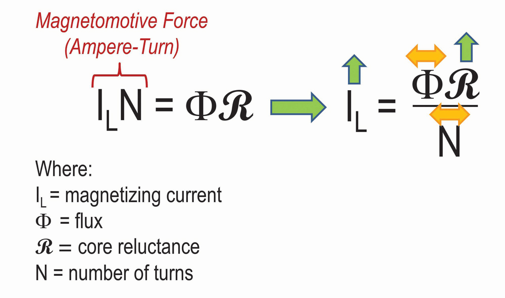
Since the flux produced by exciting the outer phases must overcome a higher effective core reluctance than that of the flux produced by exciting the middle phase, the outer phases require a higher exciting current (IL) to produce the same flux. In other words, for a given voltage, it takes more current from the source to produce the necessary flux to maintain the required volt-per-turn for the outside phases than for the middle phase. The relationship between the current component responsible for flux creation and reluctance is shown in Equation (1). Since the current is directly proportional to reluctance, the higher the reluctance, the higher the required current.
This difference in reluctance is what develops the expected high-low-high phase pattern for most large, three-phase transformers with a three-legged core (Figure 2).

Equalizing Core Reluctance
To obtain consistent exciting current measurements across all three phases, it is apparent that we must equalize the effective reluctance of all three phases during each single-phase test measurement. This is accomplished by shorting a winding of an outside leg not under test from either the high- or low-voltage side for each single-phase measurement. The action of shorting a winding removes that leg from contributing to the effective core reluctance encountered by the flux generated by the excited winding (Figure 3) by removing the necessity of the flux to maintain the volt/turn of the shorted winding (voltage drop across a short is 0 V).

With the effective reluctance of the flux path for outer and inner phases being the same, all three phases would therefore be expected to have the same current and loss measurements (Figure 4).

The advantage of this minor addition to the test configuration is now clear: Any subjectivity previously associated with the measurement for the center phase is removed, and a direct comparison of the current and loss measurements can be made across all three phases. With only a few considerations, the test setup is the same as is currently performed for traditional single-phase exciting current and loss measurements. Understanding these differences and the effect they can have on the resulting measurement is key to effectively performing this modification to the test procedure.
Shorted-Phase Selection: Outside Core Legs vs. Inside Core Leg
As shown previously, shorting one phase effectively removes the influence of that core leg from the measurement for that phase. Since the purpose of this method is to equalize the effective core reluctance for all three measurements, it is important to select the appropriate core leg for shorting for each single-phase measurement. For example, the shorting of an inside phase does not have the desired effect of equalizing the reluctance (Figure 5). Therefore, it is important to only apply the shorting technique to outer phases.

Testing Delta Winding Configurations
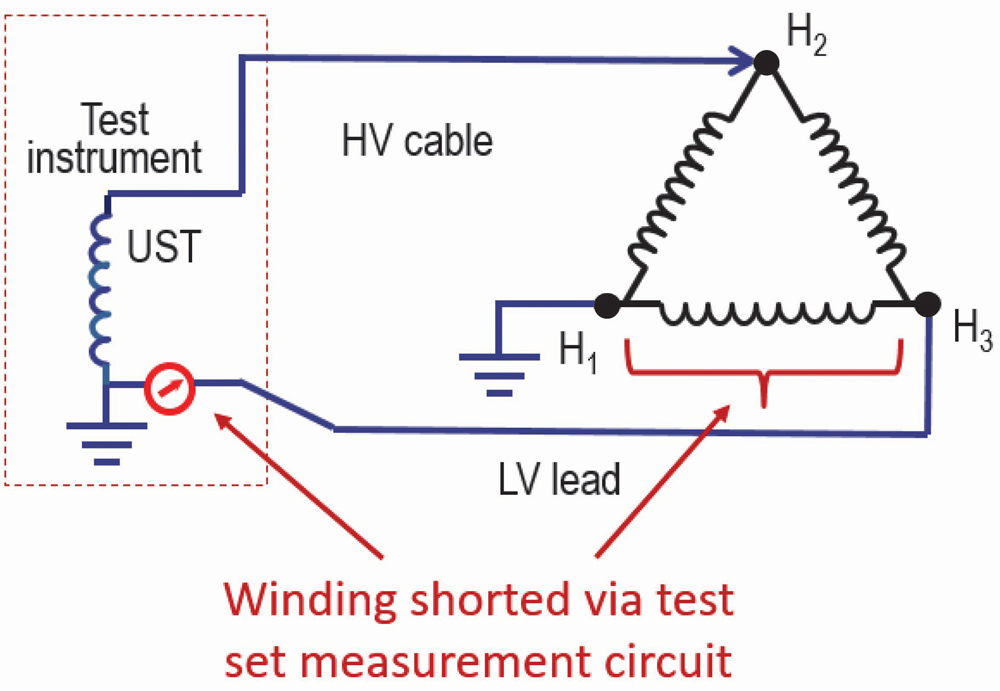
When testing a unit with a delta-connected winding, the standard test setup already shorts one of the phases via the measurement circuit, thus blocking the flux from going through the corresponding core leg (Phase H1-H3 in Figure 6). This achieves the objective of restricting some of the core segments from participating in the test. The shorting of one more phase would essentially transform the open-circuit test into the short-circuit test, thus defeating the purpose of testing the magnetizing circuit. Because of this, the shorted phase method can only be applied to wye-connected winding configurations, except for those wye-connected windings with an inaccessible neutral.
Test Setup
As previously discussed, shorting of the winding can be from either the high-voltage or low-voltage winding as long as the shorted-winding is in a wye configuration, with an accessible neutral, is an outside phase, and is not the winding under test.
While it is typically preferable to perform the shorting from the same side being tested, shorting from the opposite winding is acceptable, and there may very well be instances where it is necessary. If the option to short from the opposite winding is made, understanding the nameplate vector diagram is essential to the successful execution of this test method. The recommended test connections provided (Figure 7) are for illustration purposes only and may not apply to every transformer configuration shown. The actual nameplate vector diagram must be verified for each apparatus.

Data Analysis
For this discussion, tests for all examples were performed by shorting one phase of the opposite winding.
McGraw-Edison 230/13.8 kV, 187.5/196.8 MVA, Y-D Transformer
- DETC/LTC position: 1/N
- Test voltage: 10 kV
- Two tests were performed in the same DETC/LTC position (Figure 8):
- The first test was performed using the conventional test method, resulting in the expected high-low-high pattern.
- The second test was performed utilizing the shorted-winding method, resulting in three similar measurements.

With three similar measurements, any uncertainty with the center phase measurement is removed from the analysis.
Waukesha 115/13.09/7.2 kV, 16.8/22/4/28 MVA, Y-Y-D Transformer
- DETC/LTC positions: 3/N, 1R, and 2R
- Test voltage: 10 kV
- Testing was performed twice in all DETC/LTC combinations for both tests:
- Conventional test method results follow the expected high-low-high pattern for a given DETC/LTC combination (Figure 9).
- Shorted-winding method results show three similar measurements across all three phases for a giving DETC/LTC combination (Figure 10).


These results show that shorting one of the outside phases on one of the two low-voltage windings is sufficient to produce the desired effect.
Carte 34/4.16 kV, 1500 KVA, D-Y Transformer
- DETC/LTC position: B (no LTC)
- Test voltages: 10 kV and 0.5 kV
- Testing was performed twice, once from the high-voltage winding and once from the low-voltage winding (Figure 11):
- The test was performed from the high-voltage winding at 10 kV using the conventional test method, producing results in the expected high-low-high pattern.
- The test was performed from the low-voltage winding (due to high-voltage winding being delta-connected), at 500 V (results shown in 10 kV equivalent) utilizing the shorted-winding method, resulting in three similar phase measurements.

In this example, the high-voltage winding is delta-connected; therefore, the unit must be tested from the low-voltage wye-connected winding when utilizing the shorted-winding method.
In the conventional and shorted-winding tests, notice that one or more of the current measurements are capacitive due to the insulation system current in nature, as identified by a C in the L/C column. Only when the current is inductive, as identified by an L in the L/C column, can we apply the expected high-low-high phase pattern of the conventional test and the three similar measurements of the shorted-winding method to the current measurements (mA). In instances such as this, we must rely solely on the loss measurement for the analysis, as we have no way of predicting the nature of the capacitive component, and therefore the current measurement should not be used.
For the conventional test method, the loss measurements are acceptable, exhibiting the expected high-low-high pattern with the two outside phase high measurements exhibiting an approximately 10% difference in the current and loss measurements. For the shorted-winding test, the loss measurements are all approximately the same with less than 2% difference between the highest and lowest measurement. In this instance, not only did the shorted-winding test method remove any uncertainty associated with the center phase measurement, but it also brought the two outside phase measurements closer to each other.
CONCLUSIONS
By shorting one phase of a three-legged core-form transformer with at least one wye-connected winding (accessible neutral), the core reluctance is equalized. Assuming no core damage or other underlying fault conditions, the resulting current and loss measurements would then also equalize, removing any uncertainty associated with the center phase measurement and its comparison with the outside phases. OK, so what? How and under what circumstances would this test procedure be utilized in the field?
- It is not intended that this procedure would replace the current method of high-low-high phase-pattern analysis, but rather to simply enhance the current method of testing and data analysis. The current method of analysis works just fine for the vast majority of testing, even with the inherent ambiguity of the middle phase current and loss measurements.
- Second, the primary purpose of the exciting current and loss test is to evaluate the core magnetic circuit. Shorting removes a portion of the core influence from the measurement, so by the very nature of the test method, we are eliminating part of the very circuit we intend to evaluate.
As with any test and the resulting diagnostics, the shorted-winding method also has limitations. As discussed, it can only be performed from a wye-connected winding with an accessible neutral. In addition, the shorting of any winding adds an element of loading to the winding, which in turn results in an increase in necessary current from the source. Depending on the capabilities of the test instrument, it may not be able to provide the necessary current to maintain the volt-per-turn of the excited winding. For some transformers, particularly smaller units, inserting the shorted winding will introduce too much load for the test instrument to overcome, and it will not be able to support the test. We always want to perform the exciting current and loss test at the highest voltage we can within the capabilities of the test instrument while at the same time not exceeding any voltage rating of the apparatus. With the shorted-winding method, that may not always be possible.
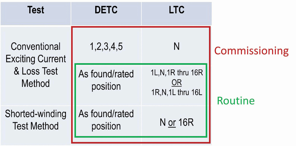
So, when would it be recommended to perform this test method? The most logical time to perform this test is during commissioning/acceptance testing as part of the initial benchmarking and also as part of routine testing.
In addition to the normally recommended testing and subsequent pattern (DETC pattern, LTC pattern, and phase pattern) evaluation, perform one additional set of three, single-phase tests using the shorted-winding method (Figure 12). The specific DETC/LTC combination for this final test could be at the discretion of the tester. If the expected high-low-high phase patterns are observed for the conventional test results, then it is safe to assume that the results of the shorted-winding method would be consistent for any DETC/LTC combination. The shorted-winding method has the potential to identify faults that impact all DETC/LTC combinations on the middle phase but are hidden simply because the middle-phase measurements are lower than those of the two outside phases. If this situation were to exist, then any position would be sufficient, as the acceptance criteria are three similar measurements for current and loss.
Another potential contribution is as an investigative test when measurements have not changed consistently between test sessions. Referring to the hypothetical example of an initial benchmark test exhibiting the expected high-low-high phase pattern with four possible routine test result scenarios (Figure 13), the inherent limitation of the current phase-pattern method of analysis is presented.
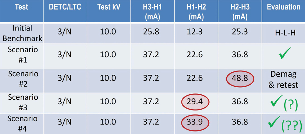
- Scenario #1. Although the current measurements have increased from the initial benchmark test, the results would be considered satisfactory as they still exhibit the expected high-low-high pattern and the current has increased by a proportional amount on all three phases. While the proportional increase in current is not an official acceptance criterion, it does provide an additional level of confidence that the results are due to a non-fault-related condition. In this case, the most likely cause is residual magnetism (residual magnetism has the effect of increasing core reluctance, which increases exciting current).
- Scenario #2. While the results still exhibit a high-low-high pattern, the two outside phases do not agree as well as they did in the initial test. In this instance, as in Scenario #1, the initial assessment would most likely be that the observed results are potentially due to core residual magnetism. However, because of the potential uneven magnetic state of the core, unlike Scenario #1, these results are not acceptable and demagnetization and re-testing would be recommended. If demagnetization did not correct the problem, further investigation would be required. The key takeaway for the example and this discussion, however, is the fact that this discrepancy is easily identifiable. Because the outside phases are involved, it stands out as a potential issue that requires further action.
- Scenario #3 and Scenario #4. Both results still exhibit the expected high-low-high pattern, but in these instances, the middle phase currents have increased significantly more than those of the outside phases. At first glance, these results would be considered acceptable, as they exhibit the expected high-low-high pattern. But are they really? As was the case in Scenario #2, these scenarios could also be due to residual magnetism and an uneven magnetic state, in which case the initial recommendation of demagnetization and re-testing would be appropriate.
More importantly, would the operator even notice the difference or simply rely on the software to rate the results? What if it was noticed, but demagnetization did not resolve the discrepancy? In short, what else could you do to provide confidence that the current and loss measurements of the middle phase are not potentially hiding a fault?
By adding one additional test line to the current commission/acceptance and routine testing recommendations, discrepancies in the middle-phase measurements could potentially be identified even if not initially recognized by the operator or the testing software.
In summary, the shorted-winding method, performed in conjunction with conventional exciting current and loss test measurement and results analysis — either as part of the battery of commissioning tests or as an investigative test — helps provide a more thorough assessment of the transformer electromagnetic circuit. In the most severe cases, it could potentially help identify faults that might go unnoticed during normal routine data analysis, especially if the user is relying solely on test software for confirmation of the results.
At a minimum, the test method can be used to provide a better understanding of the physics and impact that shorting has on not only the exciting current and loss test, but also on turns ratio (TTR), leakage reactance and loss, and SFRA, which in turn can assist in recognizing actual fault conditions such as shorted turns and tap changer issues.
Experience with the test method is limited because it has not been widely used in the field to date. Therefore, the available results are also limited. To further evaluate the benefits, you are strongly encouraged to try it out and see what you get, as only through practical application in the field will the full value of the methodology be understood.
REFERENCES
[1] Rickley, A. L. and Clark, R. E. “Transformer Exciting Current Measured with Doble Equipment “(A Progress Report),” Minutes of the Thirty-Fifth Annual International Conference of Doble Clients, 1968, Sec. 6-1001. [2] Lachman, M. F. and Shafir, Y. N. “Single-Phase Exciting Current and Loss Measurement: Visualizing Physics Behind Data,” Proceedings of the Eighty-Second Annual International Conference of Doble Clients, 2015, Sec. T-5.
Mike Anderson has been with Doble Engineering Company since 2013 and is currently a Principal Engineer, Client Services, providing technical support and training to Doble clients. Anderson previously worked for Siemens Energy as a field engineer in Nuclear Field Services and served in the U.S. Navy, working in nuclear propulsion as well as aircraft carrier and submarine repair. He received his BS in nuclear engineering technology from Thomas Edison State College in Trenton, New Jersey.