

People often refer to power factor without understanding that there are two types of power factor measurement, and it is important to understand the difference between them. If you have a power factor problem, it could mean you have:
- A power factor correction problem that requires adding (or taking away) capacitors
- A combination of a power factor correction problem and harmonics that make it look worse than it is
But how do you know which problem you have? And how do you measure it?
WHAT IS DISPLACEMENT POWER FACTOR?
Displacement power factor (DPF) is what most people think of when they talk of power factor. For those comfortable with the math, it is the cosine of the angle between a driving voltage and the resulting current. For the rest of us, it is a measure of how much the driven current waveform trails the driving voltage waveform in an inductive circuit.
A few degrees of current phase lag makes very little difference in the circuit, but as that lag increases, it has an increasing effect on lowering the efficiency of the system. The relationship between increasing phase lag and the resulting lowered efficiency is expressed by the cosine of the lag angle. Therefore, rather than reporting the lag angle, we usually report the cosine of the lag angle. That provides a more meaningful understanding of whether you have a displacement problem or not.
The downward bending curve seen in Figure 1 for true power relative to apparent power is exactly the same as the downward bending curve of the cosine math function. Therefore, the cosine of the lag angle is an exact measure of how the true power component of apparent power (V x A) decreases as phase lag increases.
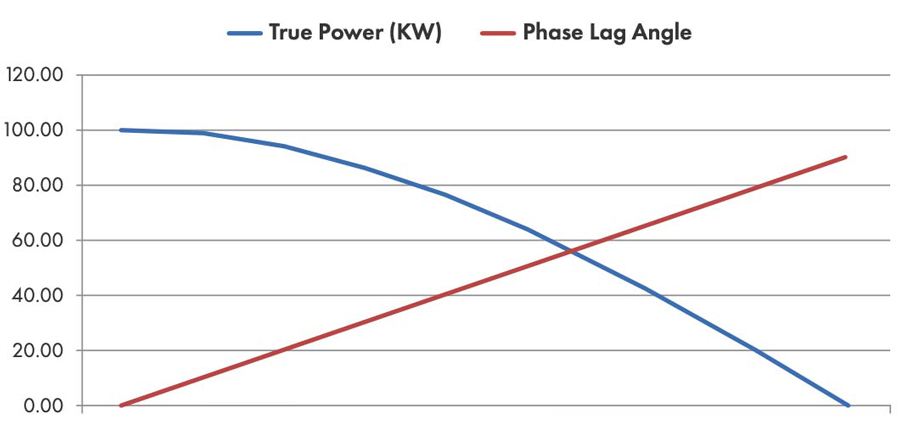
Figure 1: True Power Relative to Apparent Power
For this reason, rather than reporting the lag angle, we usually report the cosine of the lag angle (Figure 2), which provides a more meaningful understanding of whether you have a phase angle displacement problem or not. In a system where no harmonics are present, true power will be equal to the apparent power times the DPF:
W = Vrms x Arms x DPF (when no harmonics are present)
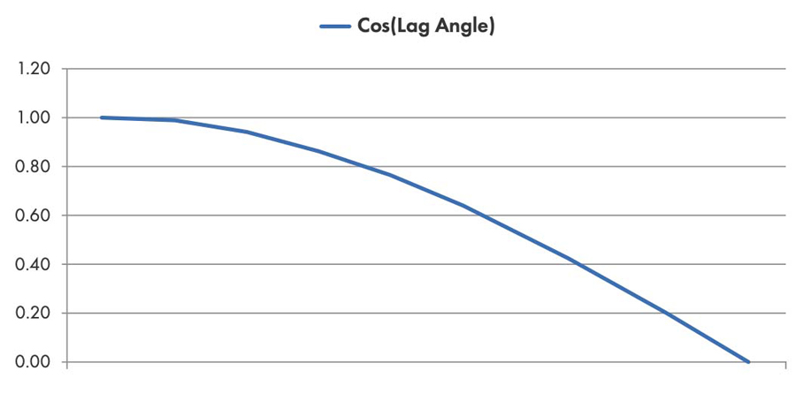
Figure 2: Cosine of Lag Angle
WHAT IS TRUE POWER FACTOR?
True power factor (TPF) is what most people actually measure. It is simply the ratio of true power (KW) to the apparent power (KVA).
TPF = W / VA (whether harmonics are present or not)
It’s easy to measure and, traditionally, it is equal to the DPF (the cosine of the phase angle). If your TPF is low, you have a problem. The only question is whether the problem is due to current displacement or due to a combination of harmonic distortion and displacement.
WHY YOU CARE ABOUT DPF
If DPF is low, it takes more current to supply the same amount of power to a load. We typically see this with motors, which are traditionally highly inductive loads. Inductance causes the current to lag the voltage.
Here is an example of how this plays out. Suppose a single-phase motor that is running off 120 V needs 1,200 W to run efficiently. If there is no phase lag, then the lag angle equals 0 degrees. The cosine of 0 degrees is 1, and the required current draw will be:
1,200 W/120 V/1= 10 A
Now, suppose the motor has very large inductance and, as a result, the phase lag angle is 60 degrees. The cosine of 60 degrees is 0.5, resulting in a current draw of:
1,200 W/120 V/0.5 = 20 A
The required current for the same amount of work has doubled because of the increased phase lag.
Figure 3 and Figure 4 are waveform captures that illustrate what was just described. The circuits in Figure 3 and Figure 4 consume nearly the same power, but the circuit in Figure 3 has a large phase lag of 60 degrees, resulting in a drop in DPF:
DPF = cos(60) = 0.50
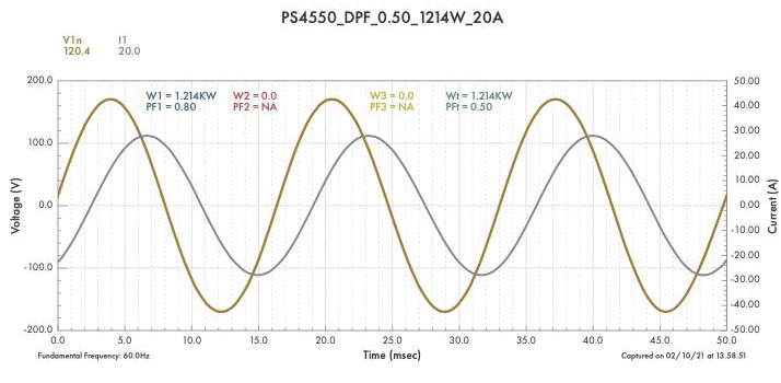
Figure 3: Large Phase Lag
The circuit in Figure 4 has no phase lag, resulting in:
DPF = cos(0) = 1.00
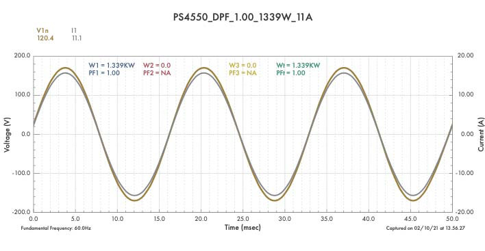
Figure 4: No Phase Lag
The circuit with large phase lag (Figure 3) requires about twice the amount of current (I1 = 20 A) to supply similar power compared to the circuit with no phase lag (I1 = 10A) in Figure 4.
A single load with low DPF is usually not an important thing, but what if there are 1,000 such motors? Now the utility must supply twice the current to accomplish the same amount of work as if there were no phase lag. The user doesn’t mind, because in most cases, they are paying for true power (KW) not apparent power (KVA). But the utility is unhappy because now their distribution system is carrying twice the current that is actually needed to perform the work for the customer. That extra current results in twice the resistive power loss in their distribution system, which benefits no one.
A similar problem arises for the end user if:
- Larger gauge conductors are required to supply the required amperage.
- The facility is remote and the owner must supply an oversized distribution system of considerable length.
- The facility is geographically dispersed (such as for oil-well pump jacks or distributed fluid pumps).
Since they do not want to absorb the cost of inefficiency, the utility fights back with a power factor surcharge on your bill so you will share their pain. This surcharge can be pretty steep, so power factor correction circuitry to lower the required current and eliminate power factor correction surcharges (or lower the cable gauge requirements in your dispersed or remote facility) may be a money-saving investment.
WHY YOU CARE ABOUT TPF
TPF is often nearly equal to DPF, so if you care about DPF, you probably care about TPF. The two measurements deviate from each other when harmonics are present. In the modern era of non-linear loads and electronic power supplies, significant harmonics can be present. If the harmonic currents are not in phase with their harmonic driving voltages, then the true power (the KW) will be less than the apparent power (the KVA), and the resulting TPF will be lower than 1.00.
If you are monitoring a conventional motor without a variable speed drive (VSD), you will find that TPF is a pretty good measurement of DPF, so talking simply of power factor (PF) is usually accurate and explanatory. But if you are monitoring an electronic load with high harmonics, there is a good chance that the DPF (the phase lag of the fundamental frequency) is close to 1.00, even if the TPF is much lower. Therefore, you should know your load before you make assumptions about what the TPF means.
To illustrate, Figure 5 and Figure 6 show waveform captures from two different single-phase simulations. Both circuits have a TPF of 0.93 with 12 A. However, they are completely different situations that require completely different mitigation methods if you want to raise the TPF.
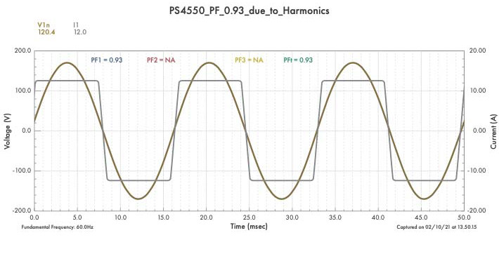
Figure 5: No Phase Lag; High Current-Waveform Distortion
The circuit in Figure 5 has no phase lag, but it has high current-waveform distortion that results in W/VA = 0.93. The circuit in Figure 6 has no harmonic distortion, but it has 22 degrees of phase lag, resulting in W/VA = 0.93. The voltage and current RMS values are the same in both circuits. The W and VA are also the same, but they represent completely different challenges for mitigation.
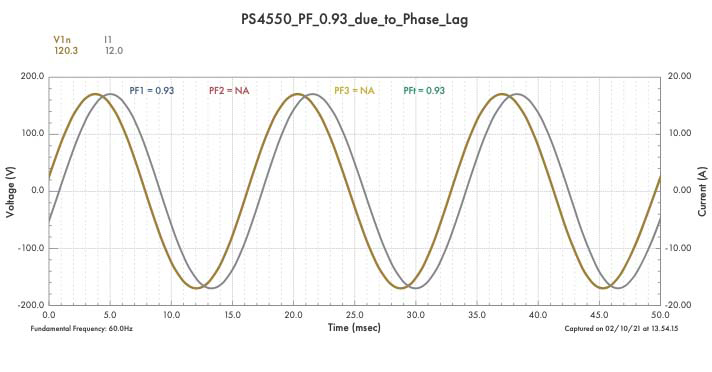
Figure 6: No Harmonic Distortion; 22 Degrees of Phase Lag
Looking closer, we can see the harmonic distortion content of the two circuits. We can see that the simulation in Figure 7 has current total harmonic distortion (THD) of 39%. The simulation in Figure 8 has THD of 0%.
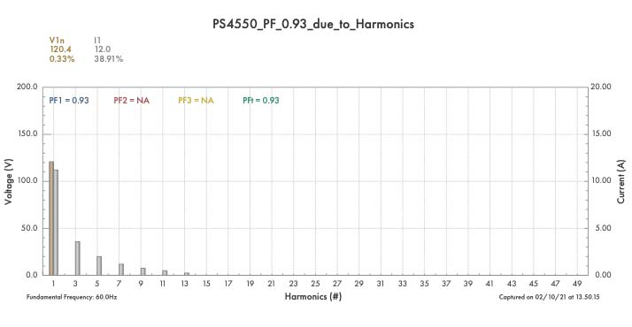
Figure 7: Total Harmonic Distortion of 39%
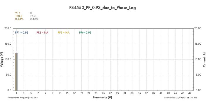
Figure 8: Zero Total Harmonic Distortion
To complete this analysis, we can see the phasor diagrams for the two single-phase simulations. Figure 9 shows no displacement (DPF = 1.00). Figure 10 has 22 degrees of displacement (DPF = 0.93).
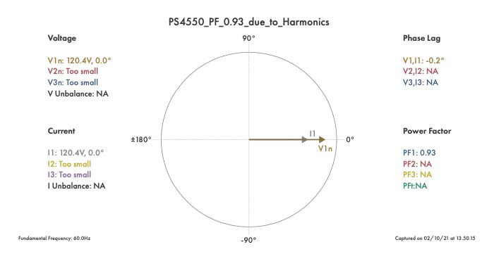
Figure 9: No Displacement
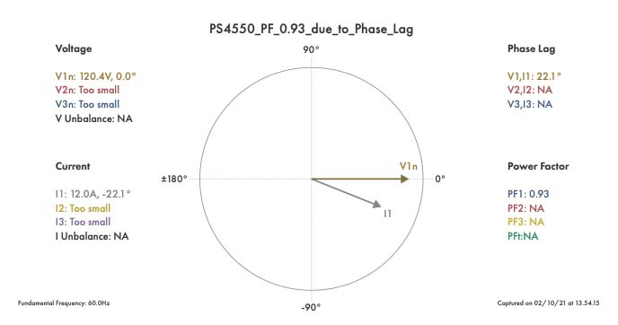
Figure 10: 22 Degrees of Displacement
Does it Matter?
If you have high harmonic content, it may not matter. A desktop computer with a low TPF due to harmonics probably makes no difference to your facility. But if you have 1,000 desktop computers with low TPF due to harmonics, you likely have substantial harmonic currents flowing through your facility wiring and through the distribution and step-down transformers at your site.
You care about this because harmonic currents have a heating effect that is far greater than currents of the same magnitude at the fundamental frequency. So you may measure an overall current of 200 A and feel safe, but the wiring in the cable trays and walls may be dangerously heated. Your distribution transformers, if not properly K-rated, may be overheating and in a dangerous condition, and there may be hot spots on contacts and connection points.
HOW TO MEASURE POWER FACTOR
A standard power analyzer has all the measurements you need to allow you to assess your problems and verify your solutions with regards to power factor.
Most power analyzers will measure and log TPF — true power factor. If you are monitoring an inductive load, this gives you a good measurement for DPF — displacement power factor — so you can take proper mitigating measures. If you are monitoring an electronic load, branch circuit, or service entrance, you can get a sense of whether a displacement and/or harmonic problem is present.
Simple calculations can guide you to make the proper choice of power factor correction equipment and verify that such equipment is performing correctly. A good power analyzer will log the true power (KW), the apparent power (KVA), the average reactive power (KVAR), and the true power factor (TPF). An analyzer that will also log the signed (+/-) DPF so you can verify the actual phase lag (or phase lead) of current in each phase over time is ideal.
Most analyzers measure DPF and display readings either on the analyzer itself (so you can take a direct measurement while wearing PPE with the analyzer in your hand) or on PC software. Analyzers with waveform capture, phasor diagrams, and harmonic bar charts allow you to directly see the components of displacement and harmonics. Most analyzers also measure and log the THD of each voltage and each current so it is clear whether there is a harmonics issue or not.
Most analyzers will log the THD of each voltage and current so you can recognize and size the scale of your harmonic problems. Some analyzers allow you to capture waveforms at any time and then transform the waveform into a harmonic breakdown of the magnitude of each harmonic frequency, so you can decide whether you wish to trap specific frequencies or filter the full range of frequencies. Logging individual harmonics can be beneficial in designing a harmonic trap for a specific harmonic.
When you mitigate, you will be able to verify the effectiveness of the mitigation by examining the log or waveforms. Of course, if low TPF is the result of both harmonics and current lag, your power analysis software will need to separate the two causes so you can select the correct mitigation action.
A solid report-creation wizard can provide summary reports of before and after mitigation. It can also provide comparison reports where the before and after are compared directly, with percent improvement shown.
CONCLUSION
Power factor is often referred to without understanding that there are two types of power factor measurement, and it is important to understand the differences. It is equally important to know how to measure and analyze power factor effectively and accurately. Choosing the right power analyzer to meet your needs will allow you to assess your problems and verify your solutions.
 Ken Kious is Founder and President of Summit Technology, Inc. He has a BSEE from UC Davis and an MS in Management from MIT. Ken has spent 30 years worrying about customers’ success in doing power measurements and has created numerous unique solutions for monitoring and analyzing electric power.