

Along the extensive and complex electrical system infrastructure from generation to transmission and distribution, the wide variety of medium- and high-voltage circuit breakers (MV/HV CB) vary in size, interrupting medium, number of breaks per phase, and various other attributes.
To help classify breakers and their attributes, they are all shipped with a nameplate stating the minimum information about specific mechanical, physical, and electrical characteristics that is required by IEEE Std. C37.04. Although manufacturers are only required to provide the minimum information, some provide more detailed information than others.
Viewing the nameplate yields a variety of information concerning the CB’s function, electrical characteristics, and expected performance. For example, the same breaker may have different types of operating mechanisms, and this might not be apparent when first looking at the nameplate. Further investigation would be needed to fully understand the breaker’s mechanism specifications.
Understanding the information provided on the nameplate provides a general description of the CB’s mechanism and operating conditions. Since there are many types of CBs, as well as numerous manufacturers, several questions can provide helpful information:
- Do all nameplates provide the same information?
- What is the minimum information that must be stated on the nameplate?
- One important specification on the nameplate is interrupting time. Does this correlate to operating times measured while testing?
- Will a quick glance at the nameplate tell you everything you need to test on the CB and what the expected values are?
Part 1 of this article in the Winter 2021 issue of NETA World focused on the HV/MV CB nameplate information that is necessary for testing purposes. IEEE nameplate requirements and definitions were discussed, and parameters that are commonly tested in the field were described along with whether the parameter is verified or measured during the design, factory, or field phase of the breaker’s life cycle.
In the end, the reader gained a basic understanding of the CB nameplate and how it relates to the application, operation, and maintenance of the CB.
Here, in Part 2, additional testing of parameters not shown on the nameplate is discussed.
Proper testing will confirm the expected performance of the CB, and the nameplate helps in preparing the test plan. Prior to and during testing, specific information from the breaker is required to prepare the appropriate test plan, accessories, and evaluation criteria. If test parameters are not given, the nameplate directs the operator to the proper instruction book for reference.
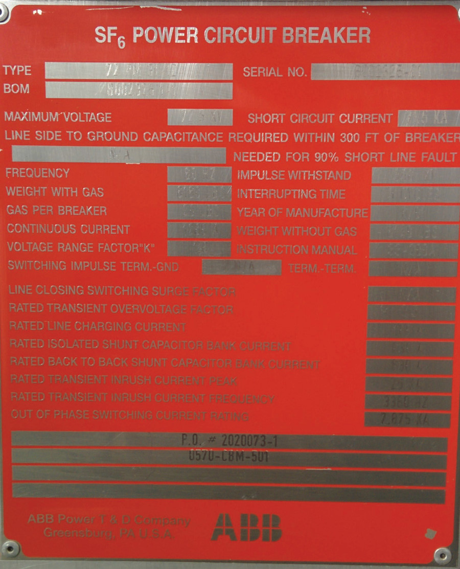
Figure 1A: Separate Nameplates for CB
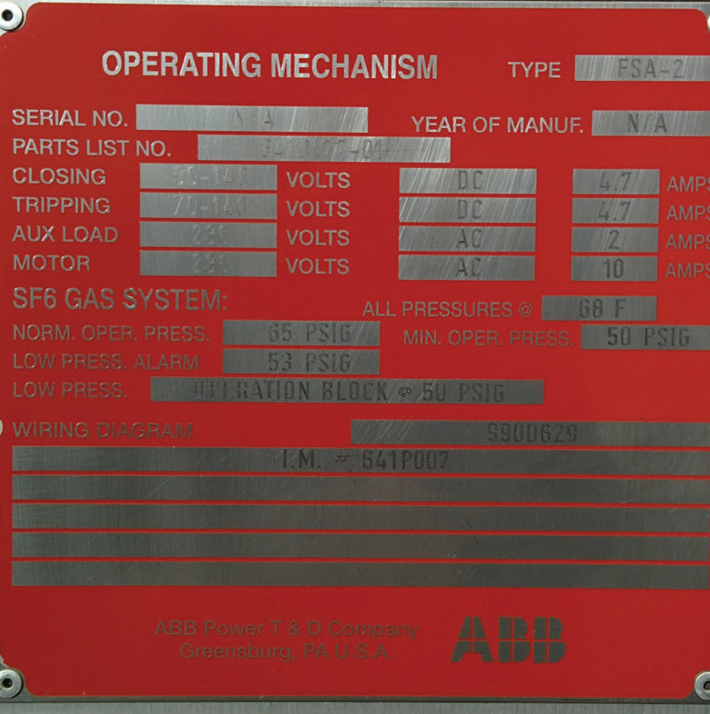
Figure 1B: Separate Nameplates for Mechanism
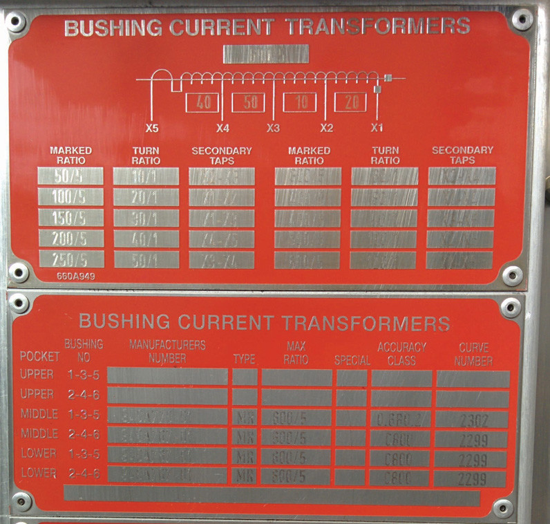
Figure 1C: Separate Nameplates for CT
FIELD TESTING NAMEPLATE PARAMETERS
Some of the electrical characteristics are not tested because they are determined by the design of the breaker. If a characteristic is tested, it may or may not be tested during the various cycles in the life of the CB.
Although most of the parameters are tested in the design and/or manufacturing phases of the CB lifecycle, only a few of the nameplate parameters are tested again in the field due to the size of the equipment needed to generate the voltages and currents required. In fact, the only CB parameters listed on the nameplate that are routinely tested in the field are related to the timing of the CB, for example, the rated operating duty cycle (i.e., O-0,3s-CO-15s-CO from the nameplate in Figure 2) and the rated interrupting time. These parameters can be measured with a time and travel analyzer, also known as a circuit breaker timer.
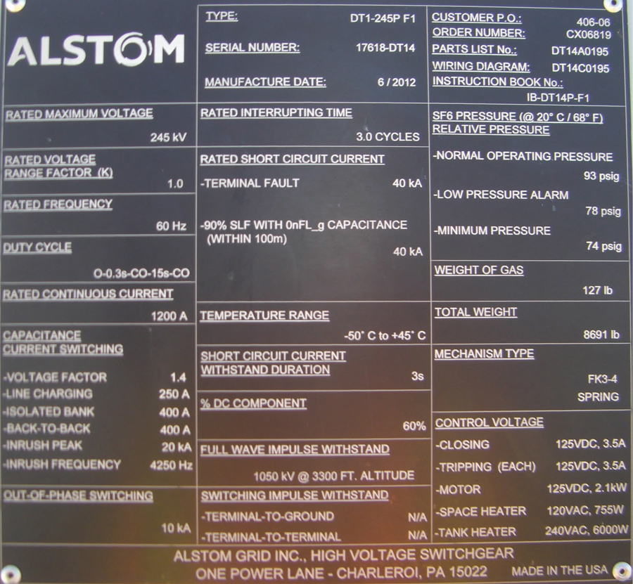
Figure 2: Combination CB and Mechanism Nameplate
It is important to note that unless otherwise stated, if the CB is pressurized, all time and travel analysis should be performed with the CB filled to the nominal pressure specified on the nameplate. In addition to providing dielectric strength, the gas in the CB also acts as a dampener during operation. Therefore, manufacturers strongly advise against operating the CB below the minimum pressure value.
Included in the control circuit are auxiliary contacts from gauges that monitor the pressure condition and will alarm or lock out the CB when the pressure condition goes out of range. These gauges are tested at the factory. No auxiliary contacts in the pressure monitoring system should be bypassed for testing purposes.
To test the duty cycle, the timing contacts of the CB analyzer are connected to the bushings of the CB. The test sequence, including the delay or reclosing times, is programmed into the analyzer. To avoid overstressing and damaging the operating mechanism during testing, these times should not be exceeded, and additional operations should not be performed within the sequence.
It is recommended to use the control power normally supplied to the CB during testing. However, if this is unavailable, an independent power supply can be used. The voltage should be set to match the control voltage that is normally used when the CB is in service. In this case, the in-service power supply must be verified separately to confirm that it will be able to supply the breaker load. The overall duty cycle should be tested, and to determine the individual operating times for the Close, Open, CO, OC, and OCO cycles, the instruction book referenced on the nameplate should be consulted.
As mentioned previously, some applications do not require an OC operation, such as generator breakers when the breakers are not designed for this sequence. Therefore, this sequence should not be simulated during testing.
The rated interrupting time displayed in the nameplate cannot be verified with a time and travel analyzer; only the operating times or contact times can be measured in the field. The difference is that under this scenario, there is no arcing taking place in the contacts. The contact times are less than the rated interrupting time, and the instruction manual on the nameplate should be referenced for the range of acceptable contact times.
In the field, contact times are measured when the control power is at nominal voltage. During these operations, the control current can be measured to verify that the peak current is within the range specified on the nameplate. Additionally, the operation of the CB should be tested at the minimum control voltage stated on the nameplate. Generally, no contact time values are given; only operation at the minimum voltage needs to be verified.
Like the minimum voltage test, CBs equipped with hydraulic or pneumatic mechanisms will have rated operating pressures. The operations of the CB should be verified at the minimum operating pressure for the mechanism. If no specifications are given for contact times, only the operation of the CB at minimum mechanism pressure needs to be verified.
FIELD TESTS UNRELATED TO NAMEPLATE PARAMETERS
Although the majority of the nameplate ratings are not verified in the field, additional tests are recommended to evaluate the condition and correct operation of the CB. While testing the CB with a time and travel analyzer, a motion transducer should be attached to the breaker in order to measure such parameters as stroke, penetration, overtravel, and velocity among others. Advanced tests like dynamic resistance measurements (DRM) can also be applied during time and travel analysis to evaluate the health and length of arcing contacts in SF6 CBs.
Most modern analyzers record close and trip coil currents; the maximum value of the coil currents is indicated on the CB nameplate. Additionally, when a control signal is applied, a characteristic current curve provides valuable information on the condition of the coil and latching system of the mechanism.
To evaluate the main contacts of the CB, a micro-ohm test should be performed where a DC current of 100 A or greater, but not exceeding the rated current of the CB, is applied to the closed contacts of each pole, and the corresponding resistance in micro-ohms is calculated.
For oil CBs, a power factor test can be performed to assess the quality of the oil and insulation system. If the CB is equipped with grading capacitors, their condition can also be evaluated with a power factor test.
With SF6 CBs, a gas sample should be taken to evaluate the moisture and purity of the insulation gas.
For MV switchgear (rack-in CBs), a regular one-minute insulation resistance (IR) test should be performed across the contacts while the CB is in the open position. With the CB closed, an additional one-minute IR test should be performed from each phase to ground and between phases to verify the integrity of the insulation.
A hipot test can also be applied to the breaker to test its insulation integrity. The hipot test setup is the same as the one used for IR testing.
CONCLUSION
CB nameplates contain basic information on how a breaker was designed and built, and it is useful to many different audiences. System engineers and operators use nameplate information for system calculations and to determine appropriate applications of the CB. System installers use it to verify conditions prior to installation.
As discussed in Part 2, testing and commissioning personnel use it to properly prepare testing procedures and evaluation criteria. Although the information displayed on the nameplate might not be complete for every audience’s need, especially for field testing purposes, most of the information is in the CB manual or instruction book, which is referenced on the nameplate.
REFERENCES
ANSI C37.06–1997, Trial-Use Guide for High-Voltage Circuit Breakers Rated on a Symmetrical Current.
IEEE Std. 4-2013, IEEE Standard Techniques for High-Voltage Testing.
IEEE Std. 100-2000, The Authoritative Dictionary of IEEE Standard Terms, Seventh Edition.
IEEE Std. C37.04-2018, IEEE Standard Rating Structure for AC High-Voltage Circuit Breakers.
IEEE Std. C37.06-2009, IEEE Standard for AC High-Voltage Circuit Breakers Rated on a Symmetrical Current Basis – Preferred Ratings and Related Required Capabilities for Voltages Above 1000 V.
IEEE Std. C37.09-1999, IEEE Standard Test Procedure for AC High-Voltage Circuit Breakers Rated on a Symmetrical Current Basis.
IEEE Std. C37.010-1999, IEEE Application Guide for AC High-Voltage Circuit Breakers Rated on a Symmetrical Current Basis.
IEEE Std. C37.012-2005, IEEE Application Guide for Capacitance Current Switching for AC High-Voltage Circuit Breakers.
IEEE Std. C37.013-1997, IEEE Standard for AC High-Voltage Generator Circuit Breakers Rated on a Symmetrical Current Basis.
IEEE Std. C37.016-2006, IEEE Standard for AC High Voltage Circuit Switchers rated 15.5 kV through 245 kV.
 Volney Naranjo joined the Technical Support Group at Megger in 2011 as an Applications Engineer focusing on the products for transformer, low-voltage and high-voltage circuit breakers, batteries, and power quality testing. He participates in the IEEE Energy Storage and Stationary Battery committee and has published articles in conferences such as TechCon, PowerTest, TSDOS, BattCon, and EIC as well as technical magazines. Volney received his BSEE from Universidad del Valle in Cali, Colombia. After graduation, he worked in the areas of electrical design and testing and commissioning of power systems as a field engineer and project manager.