
Circuit breakers are like the offensive line on a football team. Unless you have some knowledge of the game, you know they are there, but you have very little idea of what they do, how they do it, or why they do it.
Circuit breakers are electromechanical devices required to control high-voltage (HV) electrical power networks. Circuit breakers switch circuits on, carry load, and switch circuits off during routine system operation or when clearing faults on the system. Their duty as an electromechanical device — an electrically controlled machine — is unusual, as they typically stay in the closed position for long periods carrying load or in the open position providing electrical isolation. They are called upon to transition from one condition to the other only occasionally. As a matter of function, they must be reliable in static situations, but operate instantaneously when called upon to perform any switching operation — often after long periods without any movement.
The key words are electromechanical devices. Many technicians new to troubleshooting a circuit breaker think of it solely as an electrical device. Thinking of it as an electromechanical device that outputs the control of an HV system would make it easier to understand how to troubleshoot it. Simply put, a circuit has only a few mechanical requirements, and a majority of these are directly related to the operating mechanism and/or the electrical schemes that control its core function.
Circuit breaker core functions include:
- Transition from open to closed on command and remain in the closed position until commanded to open.
- Transition from closed to open on command and remain in the open position until commanded to close.
Additionally, it must accelerate the main current-carrying contacts (moving contacts) from 0 feet per second (meters per second) to specified speeds, within specified times, during the open-to-closed operation and the closed-to-open operation. It must also act as a nearly perfect conductor when closed and a nearly perfect isolator when open.
Although most circuit breakers in existence today can be described in this simplistic manner, the design of the core functions of a HV circuit breaker varies. This article provides a broad explanation of circuit breaker mechanism operation, basic troubleshooting methods, and safety issues that may occur. For the purposes of this discussion, mechanism refers to the mechanical portion with its associated latches, levers, etc.; the stored energy type (spring, pneumatic); and the electrical control and auxiliary controls, including various open and closing circuits, operating coils, and relays.
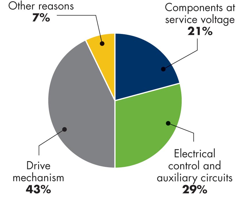
Figure 1: Component Responsible for Major Failures
Circuit Breaker Failures
This article focuses on the circuit breaker mechanism because slightly more than 70% of major circuit breaker failures involve the circuit breaker mechanism (drive and/or electrical control and auxiliary circuits).
Three comprehensive CIGRE studies on circuit breaker reliability showed two types of failures:
- Major failure. Failure of a switchgear and control gear that causes the cessation of one or more fundamental functions. A major failure results in an immediate change in system operating conditions. The backup system must remove the fault or the equipment must be removed from service within 30 minutes for unscheduled maintenance.
- Minor failure. Failure — even complete — of a constructional element or subassembly that does not result in subsequent major failure.
A vast majority (72%) of major circuit breaker failures are directly related to the drive mechanism and electrical control and auxiliary circuits; 28% are related to the components at service voltage and other reasons.
Figure 2a and Figure 2b view the data in a different manner. Figure 2a shows the circuit breaker itself (left). Figure 2b shows the general location of the components resulting in major failures.
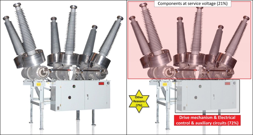
Figure 2a: Circuit Breaker ; Figure 2b: Components Resulting in Major Failures
The circuit breaker mechanism cabinet is shown in Figure 3a. Figure 3b is a simplified sketch of a mechanism/electrical control and auxiliary circuits.
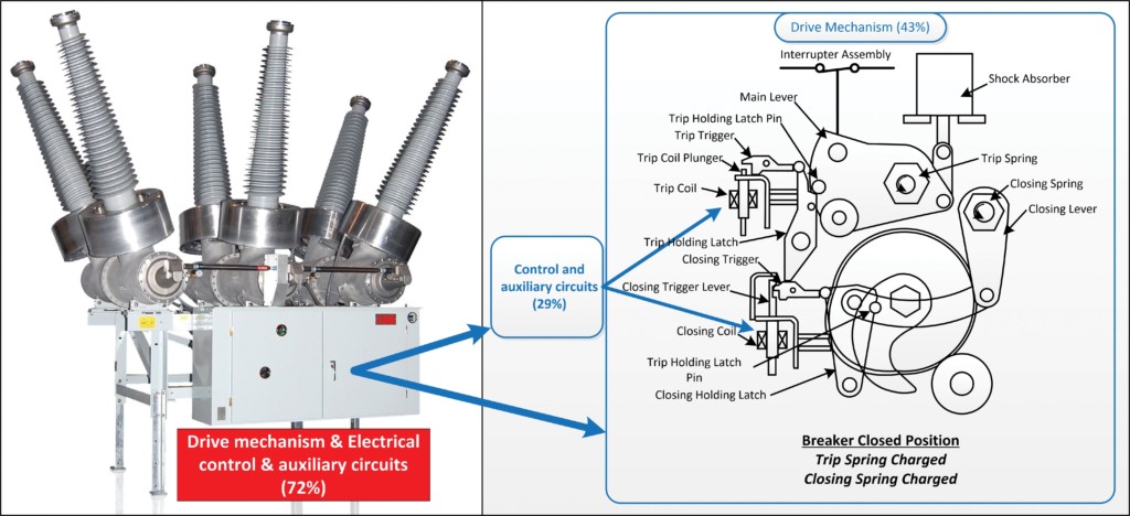
Figure 3a: Circuit Breaker Mechanism Cabinet; Figure 3b: Mechanism/Electrical Control and Auxiliary Circuits
These same CIGRE studies plotted the failure modes for mechanisms (Figure 4).
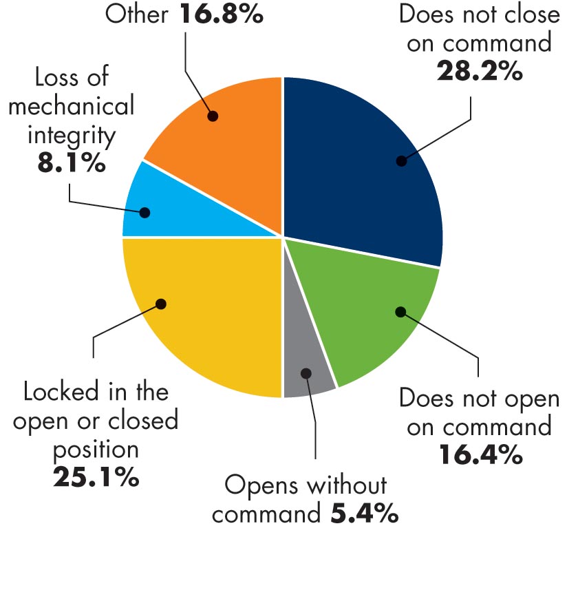
Figure 4: Circuit Breaker Mechanism Major Failure Modes (%)
Failure modes can be purely mechanical issues with the drive mechanism or electrical control, auxiliary, and auxiliary circuit issues:
- Does not close on command is likely an electrical controls and auxiliary circuit failure.
- Does not open on command is likely an electrical controls and auxiliary circuit failure.
- Locked in the open or closed position is a drive mechanism (mechanical) failure.
- Loss of mechanical integrity is a mechanical failure involving failed components (linkages, pins, bearings, etc.) in the drive mechanism.
- Opens without command may be a mechanical failure where the close latch has deteriorated or is broken, or an electrical controls and auxiliary circuit failure, where the circuit breaker mechanism was not driven far enough into the closed position for it to latch in the closed position.
- Other is anything that is not one of the above failures.
In general, the mechanism is probably the least understood and most ignored part of a circuit breaker. If a circuit breaker has been applied on a power system according to its rating, the most common major cause of a circuit breaker failing to perform its functions is the mechanism.
Spring Closed/Spring Opened Circuit Breaker
To effectively troubleshoot a circuit breaker mechanism, the technician must have a general understanding of what a mechanism does, how it does it, and why it does it. Without this understanding, how do you know whether something is performing correctly? It may be performing exactly as it is designed; you just don’t understand what it is designed to do. This section explains the operation of a spring/spring operated single pressure SF₆ circuit breaker.
Mechanical Operation
Before the circuit breaker can be closed, the mechanism must compress the closing springs (Figure 5 left). This is done by a motor/gear arrangement. The motor turns a gear that is attached to a shaft. The rotation of the shaft turns a crank arm on the shaft and compresses the opening springs. When the springs have reached the proper compression, a latch engages and holds the springs compressed (Figure 5 right), and a spring position switch de-energizes the motor. The circuit breaker is now ready to close. An indicator on the mechanism will indicate the position of the closing springs (charged).
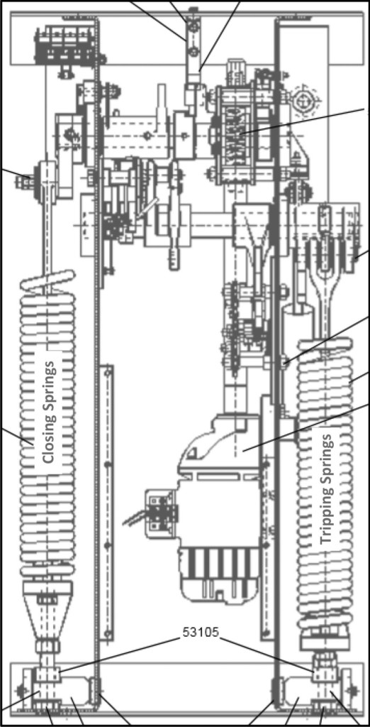
Figure 5: Mechanical Drawing: Closing Springs, Opening Springs, and Closing Spring Charge Motor
When the circuit breaker is commanded to close, the armature of the close coil moves the holding latch and the closing spring can relax to its discharged position. As the closing spring relaxes, it rotates the upper shaft, driving the main contacts closed and a crank on the tripping springs compresses them. When the mechanism is in the fully closed position, a latch engages holding tripping springs compressed, and the circuit breaker in the closed position.
With the tripping springs fully compressed, the circuit can be tripped. When a trip command is received, the armature of the trip coil releases the tripping latch and the tripping springs relax, thus driving the contacts open.
Mechanism Control Scheme Operation
The control scheme performs three functions: charge the closing spring, release the open spring, and release the closing spring on command. The control scheme also ensures the circuit breaker is in the proper state to successfully open the high-voltage circuit before it can be closed and ensure that the circuit breaker can perform only one closing operation for each close command it receives (Figure 6).
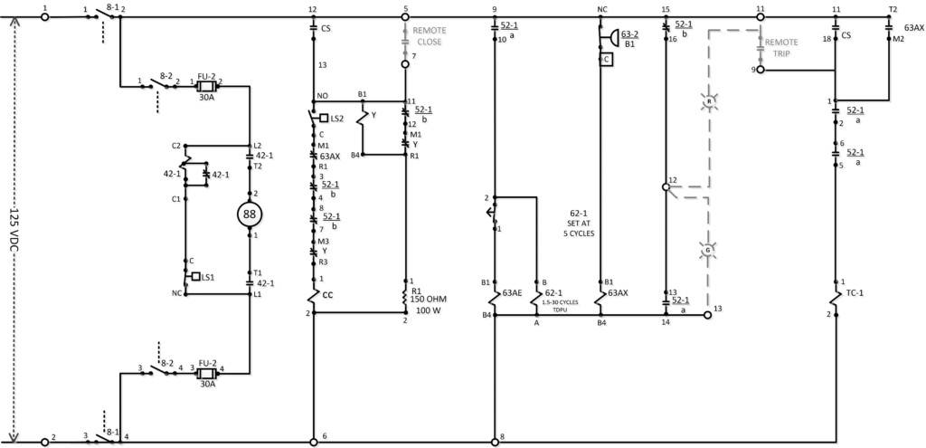
Figure 6: Control Schematic Drawn in Breaker Open and Scheme De-Energized Condition
Closing the Circuit Breaker
Assume the SF₆ pressure is at rated operating pressure. If the closing spring is charged and latched and the circuit breaker is in the open position, the circuit breaker will be operated via the local control switch. Note: The scheme will operate identically if a remote close command is received at terminal 7.
When a close command is given via the local control switch or a remote location, the close coil is energized, and this coil then unlatches the closing springs. The closing springs drive the mechanism toward the closed position. When the mechanism is nearing its fully closed position, the 52-1/b contacts in the close coil path open, de-energizing the close coil. At the same time, a 52-1/b contact opens in the anti-pump scheme (Y relay) to disable another close operation of the circuit breaker until the close command is removed and another command is issued. When the closing springs are discharged, a spring position switch in the spring wind motor closes to re-charge the closing springs.
While the mechanism is being driven toward the closed position, the tripping springs are being charged. When the mechanism reaches the closed position, the tripping springs are fully compressed, and a latch engages a pawl to hold the tripping springs compressed and hold the circuit breaker in the closed position. At the same time, the 52-1/a contacts close, and the circuit breaker is ready to perform a tripping operation.
Opening the Circuit Breaker
Assuming SF₆ pressure is within operating range, the 62 AX contact will be open. If the circuit breaker is in the closed position, the 52/a contacts will be closed. When the circuit breaker receives a trip command from the local control switch or from a remote trip, the trip coil will be energized. The armature of the trip coil will strike the tripping springs latch and the tripping springs will be released and will drive the mechanism (and the circuit breaker) towards the open position. As the mechanism travels toward the open position, the 52/a contacts will open, de-energizing the trip coil.
If, while the circuit breaker is in the closed position, SF₆ pressure drops to an unsafe interrupting level, the 63 AX contact will close, and a trip command will be issued to the mechanism and the circuit breaker will open.
Troubleshooting a Circuit Breaker Mechanism
 Safety!! A circuit breaker mechanism is a high-energy, high-speed electromechanical device capable of storing very large amounts of energy (kilo-joule and up to mega-joules). The mechanism will release its stored energy in very short periods of time (less than 0.5 seconds) by design. Consequently, a mechanism must be treated with the same respect given any high-energy, high-speed machine. Any and all safety equipment provided by the circuit breaker manufacturer must be used when troubleshooting a charged mechanism and the remote system protection/control schemes must be isolated from the mechanism whenever possible.
Even though a mechanism operation seems simple, a number of electrical relays and contacts must operate in the correct sequence, and a number of mechanical operations must occur in the correct sequence. Everything the circuit breaker manufacturer wants the technician to know about a specific circuit breaker is contained in the instruction manual, the electrical schematics and connection diagrams, and the mechanical drawings.
Generally, electrical power systems are designed and constructed to protect themselves automatically in the case of a fault. This protection will occur without human intervention. By the time the technician arrives, whatever is going to happen with the system protection schemes has already happened. The system is in the position it was designed to be in, even if a circuit breaker failed to operate correctly. This means that taking a few minutes to assess the situation will likely not make the situation any worse, but will likely aid in the troubleshooting.
Keep in mind, this is an electromechanical machine. The goal is to take a relatively complex system and break it down into its component systems.
Basic Trouble Shooting Techniques
A mechanism is a high-energy, high-speed electromechanical device that will operate each and every time it is commanded to do so with no warning if it is capable. Part of the troubleshooting situation may allow it to operate even though it failed to do so in the beginning.
When troubleshooting a mechanism that fails to operate, it is important to:
- Determine whether the circuit breaker is open, closed, or neither. Neither is a possibility if the mechanism stuck during its travel.
- Determine whether the breaker failed to open or failed to close. The first thing to check is the control voltage (terminals 1 and 2 in Figure 6). The mechanism cannot operate (open or close) if this voltage is below approximately 70 VDC on a 125 VDC control scheme.
- Did the command originate locally or remotely? This may tell the technician if the failure is in the mechanism control scheme or a remote control/protection scheme.
- If voltage measures 125 VDC, check whether the knife switches are closed and the fuses (if any) are intact.
- Determine the current state of the closing force energy.
- Does the indicator show charged?
- The closing springs must be charged and latched for a closing operation to take place. This is especially important for a failure to close situation.
- Does the failure appear to involve the control scheme and/or auxiliary circuits or is it mechanical?
- If the mechanism doesn’t operate (open or close) when commanded, careful inspection of the coil(s) involved will likely help determine the cause. When the coil (trip or close) is energized, the 52/a or 52/b contacts de-energize the coil. If the mechanism does not operate, the coil will not be de-energized and the coil will burn open. An open coil is not a cause; it is a symptom of a mechanical failure.
- What type of mechanism is it, e.g. spring close/spring open, pneumatic close/spring open?
- In the case of this specific breaker example, what is the SF₆ pressure? If the SF₆ pressure is below a defined value, a trip command is issued, and the closing command is blocked.
- Do I have access to the specific circuit breaker mechanism’s instruction book, mechanical drawings, and control schematics?
In each situation, the questions may vary significantly, and the technician will likely ask different questions depending on their level of knowledge of the circuit breaker and experience with troubleshooting. You are only looking for a likely place to begin. For example, the circuit breaker fails to close:
- The circuit breaker is open.
- The SF₆ pressure is above the trip/block close pressure.
- The closing spring charge indicator indicates discharged.
With the information gathered, and a basic knowledge of how the mechanism operates, the technician has now narrowed the search to the portion of the control scheme inside the dashed lines — the closing spring charge motor circuit. At this point, the remainder of the scheme is of no consequence (Figure 7).
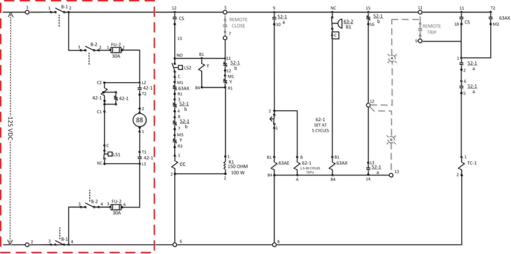
Figure 7: Control Schematic
Keep in mind that mechanical functions may be involved as well. If the electrical control scheme is proven operational, the next step is to troubleshoot the mechanical portion of the mechanism.
Start at the Beginning
1. Is there control voltage on terminals 1 and 2? If control voltage is not present, the entire control scheme will not function. The issue is upstream of the breaker.
2. Is there voltage on terminals 1 and 2 of FU-2 or 3 and 4 of FU-2?
- If the fuses are not blown, there should be 0.0 volts DC across either fuse.
- If there is voltage across either or both fuses, something downstream of FU-2 has happened.
- FU-2 fuses are 30-amp fuses. If they are blown, more than 30 amps has been flowing in the circuit. A blown fuse is not the problem, it is a symptom.
3. Are knife switches 8-1 and 8-2 closed?
- 8-1 energizes the entire control scheme DC bus.
- 8-2 energizes the close spring wind motor circuit.
4. Open knife switch 8-2 and measure the resistance of the 4-2 coil and the motor.
5. When knife switch 8-2 is closed, does the spring charge motor operate?
- If no, did the 42-1 coil operate? If no, this may indicate a misadjusted LS1 switch. This a close spring position indication switch that de-energizes the motor when the spring is properly compressed and latched.
- This could also indicate an open 42-1 coil. With a fused test lead, jumper from FU-2 terminal 4 to 42-1 terminal C1. The 42-1 contactor should operate, and the spring charge motor should begin to run. Note: The suggested point on the negative bus that is jumpered to the 42-1 coil is downstream of the fuse. This is just another point of protection for the technician and the circuit (FU-2 terminal 4).
6. Is the motor contactor (4-1) coil shorted or the motor itself shorted?
- If yes, replace the shorted unit.
- If no, replace the blown fuses.
7. Did the 42-1 contactor operate, but the motor did not run? This indicates the 42-1 contacts above and/or below the spring charge motor did not close or have high resistance. This may be remedied by inspecting and cleaning the contacts, but it may require replacing the 42-1 contactor.
8. When the spring charge motor runs, the closing spring should charge and latch, and the spring charge motor should de-energize. If the spring does not latch, the motor may just keep running and the closing spring may discharge and then be recharged over and over again. This would be considered a mechanical failure and mechanical drawings would be required.
Conclusion
Circuit breakers may be one of the least understood pieces of equipment in a power system, and the mechanism may be the least understood part of a circuit breaker. However, circuit breakers protect the system and the mechanism operates the circuit breaker. Troubleshooting requires information, knowledge and experience, persistence, and an open mind. Nearly every troubleshooting situation will take the technician on a slightly different journey than the last — and possibly the next. When the technician takes time in the beginning to gather all available information and then applies knowledge, common sense, and a reasonable plan, the troubleshooting can be done in a safe and efficient manner.
References
CIGRE Final Report of the 2004-2007 International Enquiry on Reliability of High Voltage Equipment, Part 2: SF₆ Circuit Breakers WG A3.06.
 Steve Skinner has been involved in substations since 1977. During this time, he spent 38 years constructing, commissioning, operating, and maintaining substations, with approximately 20 of these years as engineering support for the substation technicians in four operating regions of Idaho Power Co. Steve has been with Doble Engineering Company for approximately five years acting as an Implantation Engineer. He manages the Doble Circuit Breaker Seminar, Circuit Breaker Testing Fundamentals for trainers, and SF₆ Gas Handling Fundamentals sponsored by Doble Engineering and DILO.