
The clamp-on current meter that appeared in the late 20th century was a blessing to everyone working in electrical testing. It improved the vital measurement of one of the three components of Ohm’s Law by a quantum leap. No more difficult, costly, time-consuming, and potentially dangerous direct connections to live circuitry. Just clamp a pair of jaws around a conductor and read the current with digital accuracy in seconds. The clamp-on current meter quickly became so popular that it became widely known as the amprobe after the product moniker of Amprobe Instrument Corporation, its early developer — much like Kleenex and Frigidaire.
But the initial design, while an unquestionable success, still had one important shortfall: It had to be clamped on a single conductor. If clamped over a multicore cable, the phases canceled each other out and the meter read zero. That’s still a problem today. One product, the Flexi-Clamp, appeared briefly on the market, but its circuitry was top heavy and it did not survive.
Not to worry! Research and development in electronic circuitry and capability is rapid and relentless. While an easy and practical solution to splitting cable and clamping over a single conductor remains elusive, new innovation has discovered additional applications for clamping over multi-core wire.
To put a new technique into practical use, the basic technology had to be first improved with a quantum leap in sensitivity and resolution. Off-the-rack meters with a resolution of 0.1 and even 0.01 Ma aren’t good enough. Meters had to first measure with 0.001 mA resolution to enable small losses of current going to ground via extraneous paths to be recognized, measured, and traced. This unwanted phenomenon in electrical circuitry is described as “earth leakage,” which must be considered alongside the more familiar insulation leakage of current going to ground through insulating material. These leakages cause problems in circuitry and equipment such as overheating, shock, noise interference, and many others. The clamp-on ammeter seeks to measure the current going to ground not only through grounding conductors, but also finding its way through extraneous paths.
The simplest application would be to just clamp the grounding conductor (Figure 1). Even this is somewhat demanding because small currents below the threshold of common clamp-ons may still indicate a problem for sensitive electronic equipment. However, other leakage paths may be just as problematic and far more difficult to recognize and trace until now.
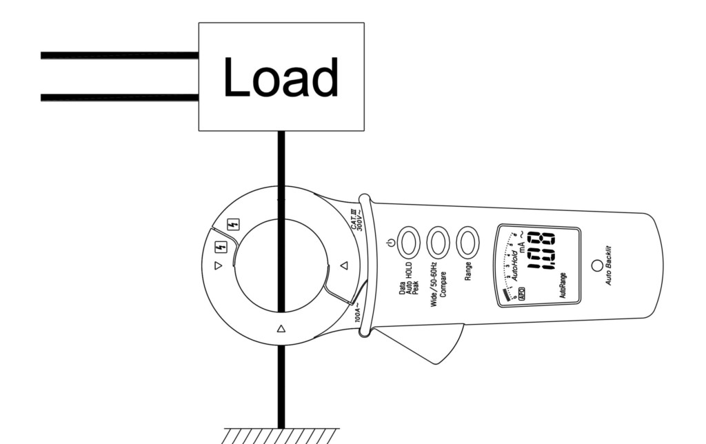
Figure 1: Direct Reading of Ground Current
A more sensitive and exploratory technique is the differential leakage test (Figure 2). This is the ability to clamp both the hot and neutral at once and measure the difference between the hot and neutral magnetic fields radiating from within the core of the jaw clamping the conductors. In the common case of hot and neutral, these fields would be 180° apart, canceling each other out and resulting in no leakage measurement. However, if a fault is present that is allowing passage of leakage current to earth, then the imbalance in hot and neutral currents produces imbalanced magnetic fields that a sufficiently sensitive instrument can detect. This will then appear on the display not as the circuit current but as the measurement of leakage current being lost.
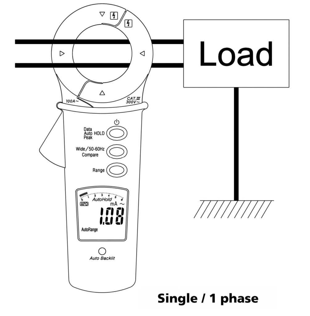
Figure 2: Differential Leakage Measurement
Differential leakage is the fundamental principle of operation of residual current devices (RCDs) and ground fault circuit interrupters (GFCIs) where a balance of hot and neutral currents equals no tripping of the protective device, while imbalance due to leakage within a circuit or appliance trips the device.
To be useful as a troubleshooting tool on the low end of the measurement spectrum, the meter must be of high quality and afford additional special features and functions to the skilled operator. Sensitivity and resolution have been mentioned, while on the opposite end of the measurement scale, range is also important to help accommodate the many possibilities that might occur during, for instance, troubleshooting an entire facility. Accordingly, both manual and auto ranging are useful to first guide the operator and then permit the operator to guide the instrument by focusing on what looks suspicious or not matching up to expectations. Of course, a true rms original is indispensable in looking for noise influences, as both pure, undistorted, sinusoidal AC waveforms and non-sinusoidal waveforms containing triangles, pulse trains, and other distortions need to be recognized and quantified.
When tracing a problem around a circuit, data hold and auto data hold are important because the operator will want to see where currents appear, disappear, divide, or in any way follow an atypical or unexpected path. Using an instrument that can keep track of such changes as opposed to doing it mentally increases speed and reduces error. This can be at the operator’s discretion or auto selected by the instrument. Peak hold similarly augments this diagnostic capability by keeping track of a suspect signal against background noise.
A low-pass filter is another useful tracing tool that enables the operator to set a ceiling on measured frequencies. This eliminates the distraction of extraneous noise by attenuating frequencies above the cut-off, filters out high frequency harmonics, and enables stable measurements. A typical cutoff frequency would be 100 Hz, with an attenuation characteristic of -24 dB per octave (Figure 3).
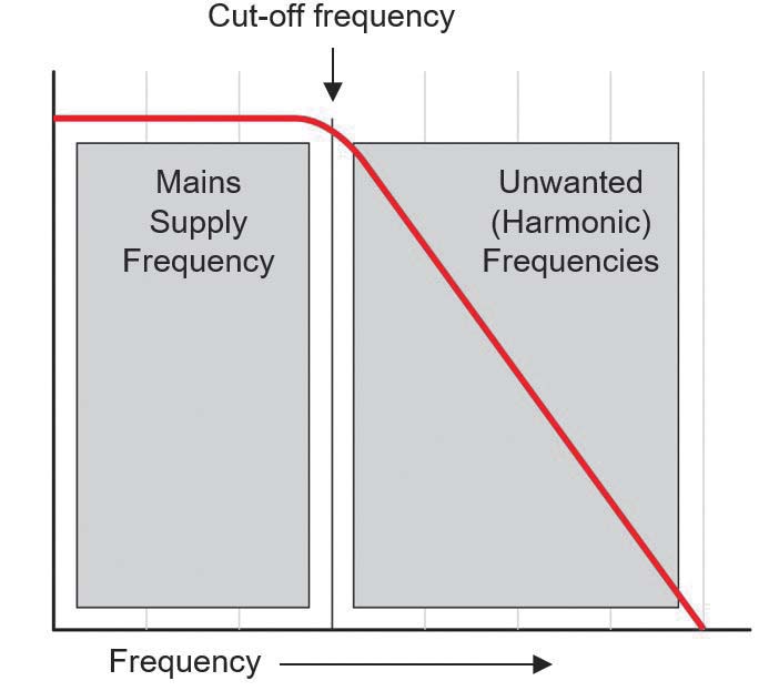
Figure 3: Low-Pass Filter
A compare feature provides another tool for the operator to trace a specific leakage path in the presence of extraneous signals from other sources. A limit value can be selected for the traced signal and the measured value automatically compared to it. It the limit is exceeded, a buzzer is activated and the display flashes. This helps the operator stay on the traced signal to origin. Manual and auto range selection similarly aids this function.
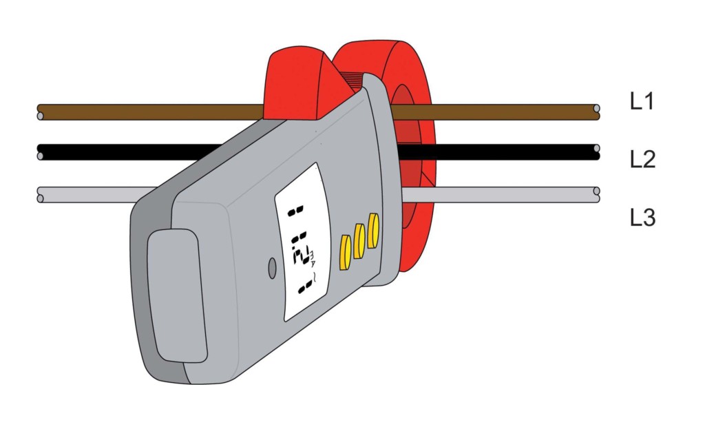
Figure 4: Differential Leakage on Three-Phase System
Single-phase earth leakage, in which the phase and neutral conductors are simultaneously clamped, is not the only possible circuit where this technology can be effectively applied. It can also be applied to three-phase conductors (Figure 4) and to three-phase-plus-neutral configurations (Figure 5). The instrument measures the magnetic fields in the clamped conductors and indicates any deviations as leakage current.
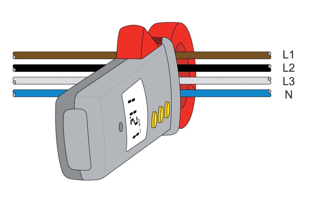
Figure 5: Differential Leakage on Three-Phase-Plus-Neutral System
Conclusion
This technique has proven useful and effective in locating and correcting nuisance tripping of protective devices. Find where the current is emanating from and eliminate it from the circuitry. While these small leakage currents may not create an issue for the operation of systems like lighting and electric motors, they can be anything from a major nuisance to a source of disruption of vital sensitive circuits that afford little or no tolerance of noise. Clamp-on tracing of extraneous current sources provides an effective means of combatting and correcting such problems.
 Jeffrey R. Jowett is a Senior Applications Engineer for Megger in Valley Forge, Pennsylvania, serving the manufacturing lines of Biddle, Megger, and Multi-Amp for electrical test and measurement instrumentation. He holds a BS in biology and chemistry from Ursinus College. He was employed for 22 years with James G. Biddle Co., which became Biddle Instruments and is now Megger.