

Performing offline electrical tests on transformers can be time consuming, especially when field measurements are not captured correctly the first time. This article identifies the electrical transformer test that technicians often struggle to perform efficiently and correctly and offers three field testing tips to address the issue. Building awareness can help test equipment users avoid situations where a significant amount of time is lost due to retesting, troubleshooting, and collaborating with test equipment manufacturers.
Power Factor Checklist
Customers seem to struggle most with the transformer power factor test, which includes an overall test, a bushing C1 test, and a bushing C2 test. The power factor test is highly sensitive to the test environment, to the lead connections, and to the test specimen’s earth-ground connection. This high sensitivity, which makes it challenging to obtain valid power factor measurements in the field, is a double-edged sword: High sensitivity makes the test a powerful tool for identifying compromised insulation (e.g., moisture ingress, contaminated oil, a bad bushing, etc.). It also makes the power factor test prone to measurement error.
To prevent wasted time, review the following checklist prior to executing any power factor measurement.
- Are the transformer tank and the test equipment solidly grounded to earth-ground potential? Failing to connect the test specimen and the test equipment to a solid earth-ground reference is the most common mistake technicians make in the field.
- Are the transformer bushing terminals completely disconnected and isolated from all cables, bus-bar, support insulators, surge arrestors, etc.? Before applying a test voltage of 10kV, establish a minimum clearance of 3 in. between energized terminals and all other surfaces. Avoid using a rubber blanket or insulated gloves to isolate the bushing terminals from external surfaces; the best insulator for power factor testing is air.
- Are the surfaces of the bushings dry and reasonably clean? Moisture on bushing surfaces can significantly influence a power factor measurement. In most cases, drying bushing surfaces with a clean, dry rag is sufficient. Use Windex or Collinite to remove excessive surface contamination from bushing surfaces.
- Are the groups of bushing terminals short-circuited together? All primary-side (H) bushing terminals must be shorted together, and all secondary-side (X) bushing terminals must be shorted together. Always use NON-insulated conductor(s) to short circuit bushing terminals; do NOT use insulated shorting leads. If insulated conductor(s) are used, the conductor’s insulation can easily become part of the power factor insulation measurement. Connect the shorting jumpers as tightly as possible from bushing terminal to bushing terminal; do not let the shorting jumpers sag and/or touch any surface other than the energized terminal.
- Remove all in-service grounds from any neutral bushing terminals. For example, remove the in-service ground connection from the X0 bushing terminal.
- Place the load tap changer in an off/neutral tap position. Some transformer load tap changers (LTCs) use a tie-in resistor, which has been known to influence power factor measurements when the transformer is tested in the neutral tap position. Federal Pioneer Electric and Federal Pacific Electric transformers with LTCs have been known to exhibit this behavior and must NOT be tested in the neutral position.
- Ensure that the exterior surface of the test equipment’s high-voltage cable is not touching any surface of the transformer at the far end where the test terminal is being energized. A conservative approach is to ensure that the last 2 ft. of the far end of the test equipment’s high-voltage cable is not touching the transformer tank, the surfaces of the bushings, etc.
- Be aware that the test environment can significantly influence a power factor measurement.
- Do not do a power factor test in the rain.
- Avoid testing in high-humidity situations where excessive moisture is present.
- Avoid power factor testing when the temperature of the transformer oil is below 0°C.
- If possible, run a power factor test after noon, when moisture/humidity are typically lowest.
The power factor checklist is intended to help test equipment users get the measurement right the first time, which is the most practical time-saving strategy. The variable frequency power factor test can be used in conjunction to quickly and easily confirm that the power factor measurements are indeed valid.
Identify Invalid Power Factor Measurements
One common scenario when reviewing power transformer test results is that the customer’s data set is provided after the technician leaves the job site and returns to the office. Review of the data frequently identifies invalid power factor measurements that now must be retested to obtain valid results.
Whether the transformer is still offline or has been re-energized, the customer has wasted significant time and resources. If the crew must return to the field to retest, more time and resources will be spent. If the transformer has been re-energized, the company has wasted their time and resources on invalid test results that cannot be used to assess the condition of the transformer.
Technicians can use the variable frequency power factor measurement to quickly identify and correct invalid power factor measurements before they leave the job site. With a power factor measurement at one test voltage and at one test frequency (i.e., with one power factor percentage value), it is difficult for the technician to verify whether the measurement is valid. However, invalid measurements often become obvious when the variable frequency power factor measurement is performed and analyzed.
A variable frequency power factor test performs power factor measurements at a series of test frequencies (e.g., 15Hz, 30Hz, 45Hz, 60Hz, 150Hz, 200Hz, 300Hz, and 400Hz). See “The Value of Performing Power Factor Sweep Measurements on Bushings” for general guidelines used to assess this test, as well as several case studies.
Case Studies
Figure 1 and Table 1 show the bushing C1 power factor measurements obtained by testing three Lapp POC 138kV bushings. Analyzing only the 10kV–60Hz power factor values, it is not obvious that the power factor measurements are incorrect. However, note that the variable frequency power factor traces for the three bushings are erratic and jagged. In general, jagged frequency sweep traces indicate invalid power factor measurements. In this case, the customer determined they had not short-circuited the primary-side (H) bushing terminals of the transformer before the C1 power factor measurements were performed on the bushings.
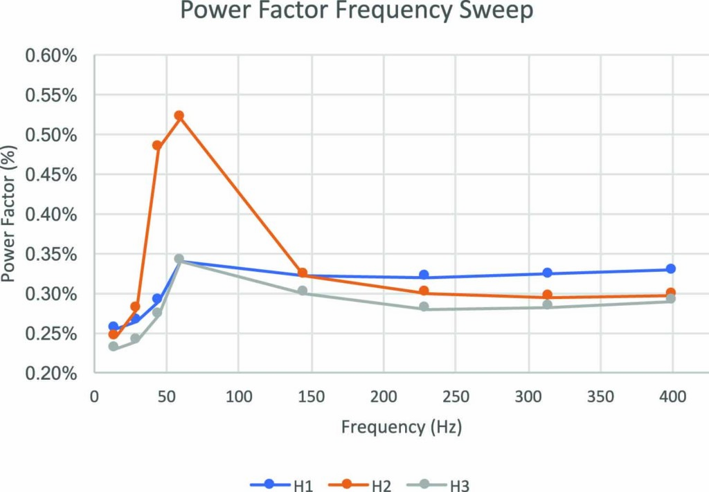
Figure 1: Variable Frequency Power Factor Results for Three Lapp POC 138kV Bushings
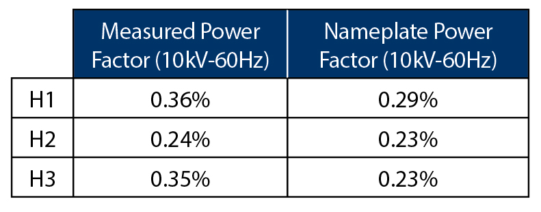
Table 1: Case Study: Lapp POC 138kV Bushings
The overall power factor measurements in Figure 2 and Table 2 were performed on a Kuhlman 118kV oil-filled transformer. The 10kV–60Hz power factor measurements look normal for an oil-filled transformer, but the variable frequency power factor traces show an abnormal CH frequency sweep trace. Note that as the test frequency increases, the CH trace approaches 0% power factor and even becomes negative. Negative power factor measurements are a telltale sign of an invalid measurement.
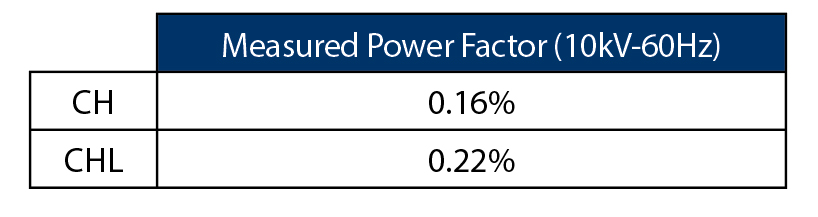
Table 2: Case Study: Overall Power Factor Measurements on Kuhlman 118kV Transformer
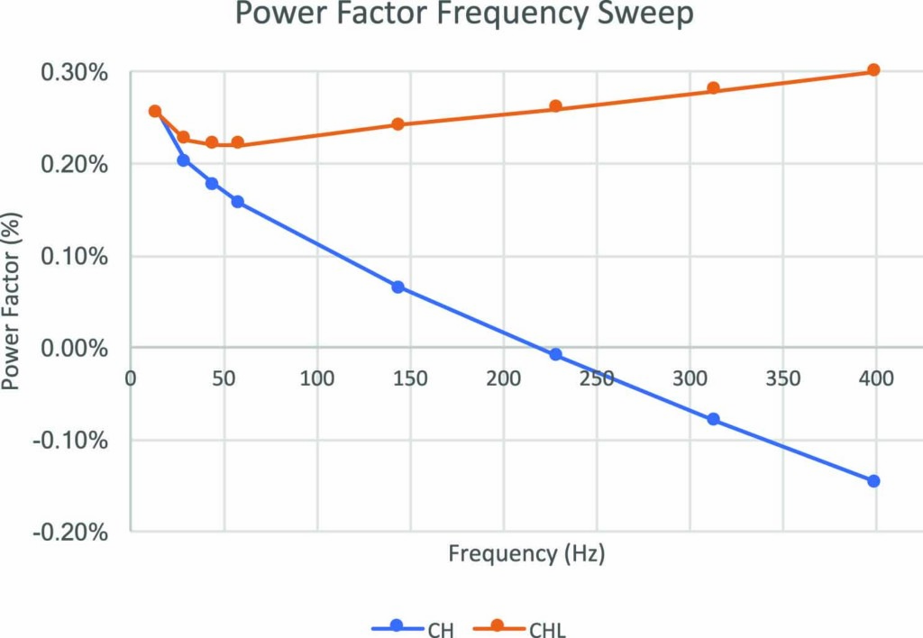
Figure 2: Variable Frequency Power Factor Results for a Kuhlman 118kV Transformer
If the technician only had access to the 10kV–60Hz power factor measurements, it is conceivable that the incorrect measurement could have been overlooked. In this case, the customer determined that the transformer tank and the test equipment were not connected to a solid earth-ground reference potential.
The technician can use the variable power factor traces to quickly identify incorrect measurements and can retest before leaving the job site with invalid test results.
Test DC Winding Resistance
Field transformer test technicians often struggle with the dc winding resistance test. The dc winding resistance test is the offline measurement used to identify bad connections and discontinuities along the current-carrying path of a transformer. This test is an invaluable tool for identifying bad connections associated with tap changers, including de-energized tap changers (DETCs) and load tap changers (LTCs).
In theory, the dc winding resistance test is a simple concept that relies on the fundamental application of Ohm’s Law (V = I x R). In practice, however, obtaining the correct transformer resistance measurements is challenging because the transformer core must be saturated. A common mistake is not waiting long enough for the core to fully saturate. When resistance measurements are captured too soon, the measured resistance values are higher than expected. This makes it appear that there is a bad connection, even when no fault exists.
The best strategy to quickly saturate the transformer core and then obtain correct resistance measurements efficiently is to inject as high as possible dc current into the winding under test. The higher the injected test current, the faster the transformer core saturates, and the faster the test can be performed. Use the following guidelines to select the appropriate test current for a given winding resistance measurement.
- The lower the resistance of the winding under test, the higher the test-current should be.
- When the winding resistance under test is greater than 100mΩ, a test current in the range of 5–10A is typically sufficient. Most resistance measurements performed on the primary-side (H) transformer winding have resistance values greater than 100mΩ.
- When the winding resistance under test is less than 100mΩ, a test current in the range of 20–30A is ideal. Most resistance measurements performed on the secondary-side (X) transformer winding have resistance values less than 100mΩ.
- In North America, LTCs are usually applied to the secondary-side (X) transformer winding. In cases where the LTC is located on the secondary side, a technician may need to obtain up to 99 resistance measurements, and the magnitude is often well below 100mΩ. In these cases, it is important to use a sizeable test current (e.g., 20–30A) so the lengthy test sequence can be performed as quickly and accurately as possible.
- The test current should not exceed 10% of the rating of the winding under test.
- The test current multiplied by the resistance of the winding under test should not exceed the maximum compliance voltage rating of the test instrument’s dc current source. In general, the higher the power the test instrument’s dc current source is rated, the higher the test current that can be injected into a given winding, and the faster the dc winding resistance test can be performed.
Conclusion
Test equipment users often attempt to apply the same magnitude test current in both the dc winding resistance H and dc winding resistance X tests. However, since the magnitude of winding resistance is often significantly different when comparing these two tests, it is conceivable that two different test currents (one for the primary-side test and one for the secondary-side test) must be applied when performing both tests. The most common mistake is not injecting enough current when performing the dc winding resistance X test; this often leads to lengthier core saturation time and inaccurate measurements, especially when an LTC is involved.
Overall, the best way to reduce wasted time when testing transformers is to get the measurement right the first time.
References
B. Dupuis, “The Value of Performing Power Factor Sweep Measurements on Bushings,” presented at WEIDMANN 2018 Annual Technical Conference.
C. L. Sweetser, “Obstacles Associated with Winding Resistance Measurements of Power Transformers,” OMICRON electronics Corp. USA.
 Brandon Dupuis joined OMICRON electronics Corp, in 2013 and presently holds the position of Regional Application Specialist for transformer testing. His focus is on standard and advanced electrical diagnostics for power transformers and circuit breakers. Brandon is an OMICRON Instructor for electrical transformer diagnostic testing theory, application, and test result analysis, including presentations and hands-on training. He is an active member of the IEEE/PES Transformers Committee. Brandon received a BS in electrical engineering from the University of Maine.