

I think it’s fair to assume that if you’re a NETA Technician taking time out of your day to read this article, you have most likely performed more than your share of medium-voltage circuit breaker testing. With that in mind, the goal is not to focus on how to test, but rather to dive a bit deeper and discuss what it is we’re really trying to accomplish when we perform the testing.
When we test hundreds, if not thousands, of breakers over the course of our careers, it’s natural to become a bit complacent and give too much credence to the process: test, record, pass/fail, next. The ultimate goal of testing is to determine whether the breaker will perform its design function within its ratings and to ensure it will continue to do so over the next testing interval. This article reviews the standard ratings of medium-voltage circuit breakers, how the designs are tested to ensure they qualify to meet those ratings, and how field testing validates that the breaker conforms to the design. Let’s start by looking at the principal ratings of a legacy air circuit breaker and a modern vacuum circuit breaker.
As you can see, many ratings apply to medium-voltage circuit breakers, and I am sure the reader is familiar with most if not all of them. I refer to the most important of those ratings as “The Big Three”: voltage, current, and short circuit.
VOLTAGE
Several voltage ratings apply to medium-voltage circuit breakers: rated maximum voltage, rated voltage, and power frequency and full wave lightning withstand voltages. Rated switching-impulse withstand voltages are present on certain specialty circuit breakers, but that is a topic for another article.
Rated Voltage
Rated maximum voltage is nearly self-defined as the highest root mean squared (RMS) phase-to-phase voltage for which the breaker is designed — the upper voltage limit at or below which the circuit breaker can interrupt safely. “RMS voltage” can be defined as the level of AC that results in the same effect of an equivalent DC. AC voltages are sinusoidal and constantly changing. Voltages listed in RMS values are noted to differentiate them from AC peak voltages.
In addition to the rated maximum voltage, there is also the rated voltage, or nominal voltage, which is the voltage at which the circuit breaker was designed to be used. When performing design testing and later field testing, the voltage we refer to is the rated maximum voltage. After all, if we ensure that the breaker can operate at the maximum voltage, it can handle any lower voltage. The ANSI/IEEE standard lists five preferred maximum voltages: 4.76kV, 8.25kV, 15kV, 27kV, and 38kV. ANSI does not specify preferred nominal rated voltages. Some manufacturers list them, but most only reference the maximum rated voltage. The rated voltages are applied at the rated power frequency. The rated power frequency is the frequency at which it is designed to operate: 50Hz or 60Hz. The dominant standard in IEEE/ANSI-rated systems is 60Hz.
It may interest the reader to learn that there is no specific design test to qualify the maximum rated voltage and rated frequency. The ability of the circuit breaker to operate successfully at rated maximum voltage and frequency is demonstrated indirectly by performing the short-circuit current interruption at the transient recovery voltage (TRV) and frequency for the given rating. We will skip over this for now and come back to it when we discuss the last of The Big Three — interrupt current.
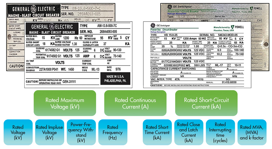
Figure 1: Primary Medium-Voltage Circuit Breaker Ratings
Rated Lightning Impulse Withstand Voltage
The remaining voltage ratings relate to insulation performance; the lightning impulse withstand voltage, commonly referred to as the basic impulse insulation level (BIL); and the power-frequency withstand voltage. If you do not already know, you can likely guess what lightning impulse withstand voltage ratings are designed to protect against: lightning and switching surges. Designing a circuit breaker with an insulation system able to withstand the 300 million volts (1.21 gigawatts!) of a typical lighting strike would be…inconceivable. Luckily, lightning surge arrestors on the system are designed to do just that. Lightning arrestors divert the harmful potential to ground, protecting the electrical system. However, as effective as surge arrestors may be, they are not perfect and do not act instantly. The electrical system is subjected to a portion of the surge; the severity depends on how far downstream of the strike the system is located. The rated BIL is the maximum peak value the circuit breaker is rated to sustain without damage — starting at 60kV peak for 4.76kV-rated circuit breakers and ending at 150kV peak for 38kV-rated equipment.
The design test to qualify the BIL rating is performed using an impulse voltage generator test set capable of generating the large voltage impulses. The circuit breaker design is subjected to 54 lightning impulses — six on each primary terminal — with the breaker open and all other terminals grounded, then six on each phase with the breaker closed and the remaining phases grounded. The impulse voltage is applied at both the positive and negative polarity, three each, for a total of six pulses. For the design to pass, it must successfully absorb the lightning impulses without flashover (Figure 2).
Figure 2: The modest-looking flashovers during BIL testing are as loud as gunshots.
There is no specific field-conformance test to directly verify the BIL rating. Impulse voltage generator test sets are not portable; quite the opposite, they are sizeable units operated in a lab setting and cost hundreds of thousands of dollars (Figure 3). Furthermore, the testing is designed to stress the insulation system and is considered destructive. Even when the test subject passes, it should not be placed into service.
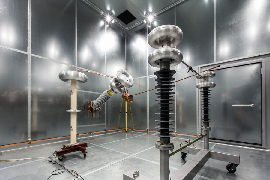
Figure 3a: Impulse Voltage Generator Test Set
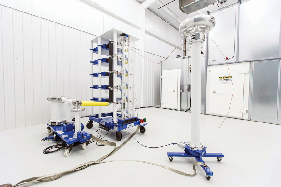
Figure 3b: Impulse Voltage Generator Test Set
Rated Power Frequency Withstand Voltage
The rated power frequency withstand voltage (often referred to as hipot voltage) is the RMS voltage that a circuit breaker in new condition should be capable of withstanding for one minute. The purpose of the hipot voltage rating, and the associated test, is to stress the insulation system. Overvoltage tests are the only known means for providing assurance that the insulation system has a specific minimum dielectric strength. The tests provide confidence that the insulation system is suitable for service for a certain time.
The test to qualify the power frequency withstand rating of the design is performed by applying the rated AC voltage for one minute on each terminal with the breaker open, and for one minute on each phase with the circuit breaker closed. During the tests, the remaining terminals/phases are grounded. Should no flashovers or visible damage to the insulation occur during the test, the design passes. Hipot voltage ratings are not typically listed on the ratings nameplate. The ANSI/IEEE RMS voltage ratings are standardized and are related to the rated maximum voltage: 19kV for 4.76kV-rated circuit breakers; 36kV for 8.25kV- and 15kV-rated breakers; and 80kV for 38kV-rated breakers.
Two primary field tests are used to verify the power frequency withstand rating and, in turn, the condition of the insulation system: The insulation resistance and field dielectric withstand tests are commonly referred to as the Megger test and hipot test, respectively. Both tests are performed in the manner described in the previous paragraph by applying high voltage and monitoring the response. During the Megger test, 2.5–5kV DC is applied with respect to ground via a megohmmeter to measure the insulation resistance. The field hipot test is identical to the design test but at 75% of the power frequency withstand voltage rating. The two tests are similar in nature but have different goals in mind. The Megger test (performed first) is performed to evaluate the condition of the insulation system. It can be used to identify trends, whereas the field hipot test is designed as a pass/fail test to cause a failure of the insulation. Most technicians, even the most experienced, may not think of it in this way — testing to cause a failure — but that is exactly what the hipot test is for. The test stresses the insulation system beyond what it is expected to see in service in the hopes that, if defective, it will fail during testing when the costs are low compared to failure while the breaker is in service, where the costs would be considerably greater.
Two additional tests are used to validate circuit breaker insulation system: power factor (pf) and MAC testing. Simply put, pf testing is a more instructive version of Megger testing. Power factor testing is a means to diagnose as well as provide a measurement of insulation condition. MAC testing is an application-specific insulation test for vacuum interrupters to provide a means of quantifying vacuum integrity.
CURRENT
The next of The Big Three is current. Like voltage, medium-voltage circuit breakers have several current ratings, but only one really applies to current; the rest apply to the short-circuit rating, which may be measured in amperage but is another animal altogether. Compared to the discussion on rated voltage, current will be a walk in the park.
Continuous Current Rating
The rated continuous current is the limit of current in RMS amperes (A) that the circuit breaker can carry at its rated frequency without exceeding the temperature limitations of the materials used in its construction. To save space on the ratings nameplate, most manufacturers list this rating as rated amps. There are three ANSI/IEEE standard-preferred continuous-current ratings in medium voltage: 1,200A, 2,000A, and 3,000A. A rating of 600A was prevalent in the past, and some manufacturers still offer it, but they are uncommon. Several manufacturers also offer 4,000A, 5,000A, 6,000A, and beyond; however, these are mostly fan-cooled for use in generator protection and other specialty applications. Regardless of the rating, qualification of the design is a simple, straightforward process.
The test to qualify the continuous current rating of the design is performed by passing the rated current through the circuit breaker; this test is commonly referred to as a “heat run.” Of course, there is an extensive list of test conditions; I will spare the reader from them, but they are meant to replicate the harshest service installation. A thermocouple is applied to the hottest accessible spot (Figure 4). However, since you can’t be 100% sure where that hottest spot is, several thermocouples are used.
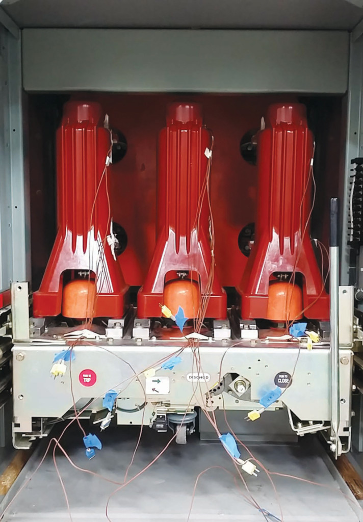
Figure 4: Thermocouple Wires on a Vacuum Circuit Breaker
The test generally runs for 4–8 hours with temperatures logged every 30 minutes (Figure 5). When the temperature rise (in respect to ambient) of any monitored point has not changed by more than 1°C for three consecutive readings, the test is concluded. If none of the material used in the design exceeds its temperature limits, the design passes. There are two temperature limits for each material type: total (highest) temperature and temperature above ambient. Prior to and after the test is concluded, the resistance of each phase is measured and recorded using a low-resistance ohmmeter, commonly called a “ductor” test.
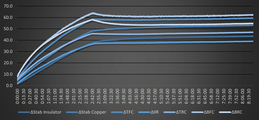
Figure 5: Medium-Voltage Circuit Breaker Heat Run Test Data. The test was performed at 3,000A on a retrofit replacement circuit breaker. Effects of ambient temperature changes have been removed.
It would not be realistic to replicate the design test in the field. Luckily, all that’s required is to verify the continuous current rating is a ductor test. The resistance of the primary circuit is measured on each phase from line-to-load, then compared to the measurements provided by the manufacturer. In the absence of manufacturer-published data, phase-to-phase measurements are compared, and high readings are investigated. Unfortunately, manufacturer data is not always available, especially on legacy circuit breakers. In the absence of manufacturer data, ANSI/NETA MTS and ANSI/NETA ATS recommend investigating any reading that is 50% higher than the lowest phase and taking actions to correct it.
SHORT CIRCUIT
Short circuit is the last of The Big Three primary ratings and the most important. After all, protecting equipment from a short circuit is a circuit breaker’s purpose: Break the circuit. The primary component of the short-circuit rating is the rated interrupt current, but it also relates to other required capabilities, specifically the close and latching current rating, the short-time current withstand rating, and the interrupting time rating. I also touch on how the short-circuit rating relates through testing to the rated maximum voltage and power frequency.
Compared to the previous ratings discussed, the rated short-circuit current is the most complex in terms of its performance expectations and how it is tested to meet them. So much so that it would not be difficult to focus this article solely on that subject. However, my intent is to focus on the aspect of the rating as it relates to the subject at hand, and I will try not to dive too deeply into the symmetrical/asymmetrical (DC-component) physics of three-phase faults nor the test parameters and how they are calculated.
The primary component of the short-circuit rating is the rated interrupt current. In industry, the terms “short circuit” and “interrupt current” are synonymous, but there is a difference. A short circuit encompasses all the related capabilities of the equipment, including the interrupt current rating. While all manufacturers are aware of the difference, they all also refer to the interrupt-current rating as the short-circuit rating, so I will do the same.
Rated Short-Circuit Current Rating
The rated short-circuit rating is the highest value of the three-phase, short-circuit current in RMS amperes that the circuit breaker is required to interrupt at its rated maximum voltage. Prior to 1999, the short-circuit rating was based upon a constant MVA over a range of operating voltages versus today’s constant kA ratings at a maximum rated voltage.
As background, the MVA rating prevalent from 1964–1999 applied to the technology of the time: air magnetic circuit breakers. The circuit breaker arc chutes were limited in their ability to insulate the high recovery voltages (TRV) experienced during fault interruption. However, if the operating voltage — and in turn the TRV — were lowered, the interrupt current rating could be increased until limited by the heat-absorption capabilities of the circuit breaker’s contacts. The voltage range factor (k-factor) is the range over which the interrupting capability increased as the operating voltage decreased; the k-factor is generally from 1.1 to 1.3. Though no longer applicable, the k-factor is sometimes present on the nameplates of constant kA-rated equipment of today, but since the interrupt rating is established at the maximum voltage and not a range of voltages, it is always 1.0.
A number of short-circuit current ratings are preferred by ANSI/IEEE standards:
- 4.76kV: 31.5kA, 40kA, and 50kA
- 8.25kV: 40kA
- 15kV: 20kA, 25kA, 31.5kA, 50kA, and 63kA
- 38kV: 16kA, 25kA, 31.5kA, and 40kA
The short-circuit current interrupt capabilities of a circuit breaker design are demonstrated by an extensive series of tests that demonstrate not only the maximum interrupt current, but all the related capabilities as well. Prior to discussing how the design test is performed, let’s get an understanding of the related ratings: the close and latch rating, the short-time current withstand rating, and the interrupt time rating.
Close and Latch Current Rating
The close and latch (C&L) current rating is the ability of a circuit breaker to close in on a short circuit and stay closed; it is measured in kA peak. The C&L rating is based on the short-circuit rating: at 60Hz, it is 2.6 times the RMS interrupt current. Why is the close and latch rating higher than the interrupt rating? The reason has to do with physics and something called the Lorentz force. Current generates a magnetic field; the more current, the stronger the magnetic field. The nature of the magnetic fields generated on the stationary and moving contacts is such that they create an opposing force between them — a Lorentz force. When the breaker closes in on a short circuit, the Lorentz force may be so strong that it prevents the breaker from latching into the closed position, but the circuit breaker mechanism (primarily the closing springs) will keep trying to close it. The contacts will chatter, and the breaker can literally explode. As you can see, C&L capability is an extremely important rating. The short-time current rating is equally important.
Short-Time Current Rating
The short-time current rating is the ability of the circuit breaker to withstand the effects of the rated short-time current level for two seconds. Compared to the C&L rating, the reasoning behind the need for the short-time current rating is straightforward: When a fault occurs, the relaying system measures its severity and, when necessary, signals a circuit breaker to trip open, isolating the fault. This process happens very quickly but not instantaneously. The short-time rating is used by engineers to determine the ability of the circuit breaker to protect itself and coordinate with other breakers in the system to trip selectively — to ensure the circuit breaker closest to the fault operates first, minimizing the effects on the entire electrical system. The short-time current rating amperage is the same as the rated short-circuit current capability of the breaker. We will discuss another short-circuit capability related to time — the rated interrupting time — next before moving on to testing.
Rated Interrupting Time
The rated interrupting time is another rating that is nearly self-defined by the term: It is the elapsed time, in cycles, between the energization of the trip coil and the maximum arcing time of the circuit breaker. The rated interrupting time is the operating time as calculated by adding the contact opening time to the maximum arcing time. In short, it is the total elapsed time from when the circuit breaker is given a signal to trip and when the current is completely interrupted. The ANSI/IEEE preferred rated interrupt time is five cycles (83ms), but three-cycle breakers are becoming increasingly common.
Now that the short-circuit ratings have been adequately explained, we can move on to a discussion of how the short circuit design rating is tested.
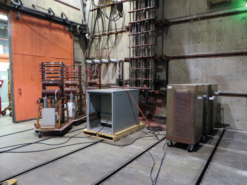
Figure 6: Short-Circuit Testing per Table 1 on a Circuit Breaker Staged for Testing in a High-Power Test Bay
Compared to all the design tests, short-circuit testing is by far the most difficult to prepare for and perform (Figure 6). Though the circuit breakers are only subjected to the high currents for an instant, the magnetic fields they generate interact, trying to rip the breaker apart. The testing is expensive, destructive, and can only be performed at a handful of high-power test labs around the globe. Furthermore, if the testing fails, it is difficult to alter the design in a timely manner. An iterative design process can be used until the voltage and current ratings are met, but few manufacturers have their own high-power lab to enable them to employ it for short-circuit ratings. The tests to qualify the short-circuit design are called short-circuit interrupting tests but are commonly referred to as “Table 1 testing.” IEEE Std. C37.09 is titled IEEE Standard Test Procedure for AC High-Voltage Circuit Breakers Rated on a Symmetrical Current Basis. As the name describes, C37.09 lists the test procedures to perform all the design testing described in this article. Table 1 in that standard lists the ten tests that must be done to demonstrate that the short-circuit rating is met.
As discussed, short-circuit is not a single rating but a set of required capabilities. Here, I will not describe all the testing required to meet them, but rather the intent. The test is set up to create the most severe switching conditions in terms of the respective ratings: the highest voltage at the highest fault current at the worst time for the longest time, multiple times! To ensure the design meets the required ratings, the circuit breaker must pass all ten tests, in order, and survive unscathed on the other side in substantially the same mechanical condition it was in prior to testing. In short, to pass, it must interrupt, sustain, and absorb everything thrown at it without blowing up in the process! To verify breaker condition following Table 1 short-circuit testing, mechanical inspection and a power-frequency withstand test are performed, the resistance of the primary circuit is measured, and the contact opening timing is verified.
As fun as it sounds, our customers prefer that we not blow up their circuit breakers when we field test them, plus it would be ridiculously dangerous and expensive, so the question becomes how can we be sure the breakers will perform when required? Which field tests validate that the breaker conforms to the design? I would argue that, while all tests contribute, it is primarily a test that gets the least amount of recognition: the mechanical inspection. When the circuit breaker’s design is qualified, the test subject(s) are in optimal condition, have been adjusted to factory specifications with meticulous attention, and are operated in a laboratory setting. They are not only new, but are also the pinnacle specimen of their design. The operating conditions of a typical service installation are far from optimal. Circuit breakers are operated in humid and sometimes corrosive environments that exceed their temperature limitations, go months if not years without operation, let alone maintenance, or are cycled beyond their required maintenance periods. Insulation systems are contaminated. Components embrittle, rust, or otherwise degrade. Lubricating oils and greases become glue or are absent altogether. Contact surfaces wear, fasteners loosen, springs relax — all these contribute to mechanism wear until it at best operates out of manufacturer specifications or, at worst, does not operate at all.
To ensure that the breaker will operate within its design ratings, it must be in acceptable physical condition with all critical adjustments set within specification. The critical adjustments and condition differ by both design and manufacturer, some of which include cleanliness, primary and arcing contact erosion/wipe/gap/pressure settings (Figure 7), puffer operation, close and trip latch wipe/travel/gap settings, control switch adjustments, blow-out coil continuity, lubrication state…and the list goes on.
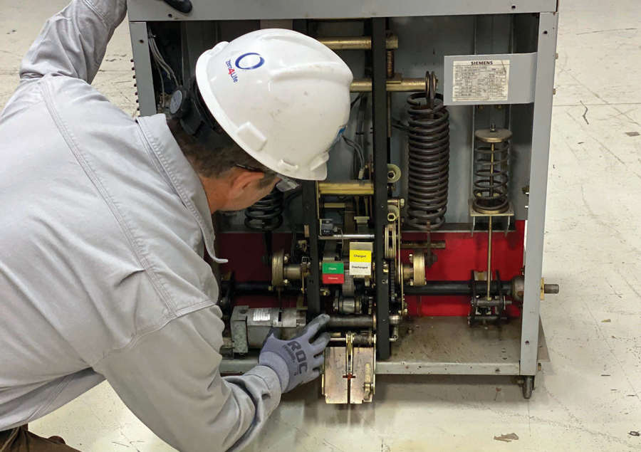
Figure 7: Factory testing confirming that settings and tolerances are within specifications is vital to ensure the circuit breaker will operate in accordance with its design.
If any of the mechanism conditions or adjustments are unsatisfactory, the breaker may still operate, but not necessarily within its design. An excellent field test used to assess the overall status of the circuit breaker is to measure its opening and closing velocity and timing via time-travel-analysis (TTA) testing. If the breaker passes all other testing, is mechanically sound and factory adjusted, and has a contact opening time that meets or exceeds manufacturer requirements, we can be confidently assured that circuit breaker’s short-circuit capability — the circuit breaker’s primary function — will perform as expected.
RATED CONTROL VOLTAGE
A final design rating to discuss beyond The Big Three may not be as impressive, but in its way, it is equally important: control power ratings. The rated control voltage is simply the designated voltage measured at the point of user connection to the circuit breaker. While medium-voltage circuit breakers allow for mechanical operation in service, they are, without exception, electrically operated devices. The ANSI/IEEE standard control voltages are 24VDC, 48VDC, 125VDC, and 250VDC; and 120VAC or 240VAC; or some combination of these voltages. Each voltage level allows for a corresponding range of operation to accommodate variations in source regulation, low battery-charge levels, as well as high floating-charge levels. For example, the range for 125VDC control power is 70VDC–140VDC for opening operations. Most manufacturers list the complete range on the ratings nameplate, but some only list the standard level. Regardless of its presence on the ratings nameplate, the range exists and must be considered.
The design test to ensure proper operation of the circuit breaker at the rated control-voltage range is demonstrated during mechanical operation tests and short-circuit switching tests. The mechanical operation test’s primary focus is to verify the mechanical endurance of the design. There are number-of-operation requirements for between servicing, no-load mechanical operations, rated continuous-current switching, and others. The numbers are based on combinations of The Big Three ratings, starting at 10,000 mechanical close-open operations at the 4.76kV–31.5kA–1,200A rating, down to 1,500 operations at the 38kV–40kA–3,000A rating. During the testing, at least 10 operations are required at the minimum control power range, and 10 operations at the maximum. Additionally, Table 1 short-circuit design tests are all performed at the minimum control voltage.
Two field tests are used to verify proper operation of the rated control power.
- The first is simply a duplication of the design test. Few manufacturers give guidance to a minimum number of required operations at the minimum and maximum range, but most technicians will agree that at least five operations at the minimum range are adequate, but 10 operations at the minimum and maximum limit is best. Like TTA testing, operating the circuit breaker at the minimum control voltage can be a useful indicator of overall circuit breaker condition and settings, especially proper trip-latch adjustment.
- The second field test is control wiring insulation resistance testing. Like the Megger test performed on the primary insulation system, though at a much lower voltage, the test ensures that minimal resistance to ground is maintained and the control system is reliable. Field testing of the control power system is rarely discussed, and its importance is not emphasized, but no matter how well a circuit breaker may be maintained, it’s all for naught if the control power system is defective.
CONCLUSION
This article focused on the ratings of medium-voltage breakers, the testing required to qualify the design, and the field testing that validates circuit breaker conformity to the design. Not all the ratings were discussed, nor every design and field test, but the principal ratings were covered. Most of those not cited apply to circuit breakers used for special purposes, such as capacitive switching and generator applications.
The goal of this article was to discuss the why of medium-voltage testing. It is my hope that the reader has learned something new and gained a new appreciation for the testing they perform on medium-voltage circuit breakers and the importance of identifying breakers that need extended maintenance, reconditioning, or replacement.
 Paul Grein has been with Group CBS since 2008, working primarily at Circuit Breaker Sales in Gainesville, Texas. He has worked with industrial electrical equipment for 25 years. His career began in the Navy as a nuclear-qualified electrician on the submarine USS Topeka SSN 754 from 1996 through 2002, followed by positions in the steel industry through 2005. Paul has a BSEE from the University of Texas at Dallas and an MBA from the University of North Texas. He participates in the IEEE/ANSI PES C37 Standards Committee, which publishes and maintains the design and testing standards that govern the industrial power equipment industry. Paul’s primary responsibilities at CBS and the Group include sales, engineering design, technical expertise, standards, project management, and engineering team management.