
“What are you doing here?” asked the manufacturer’s testing representative. “We are doing start-up of the gear, and your work seems redundant.”
Redundant? That depends on what each of us is responsible for checking. That depends on who is going to ensure that all the known potential failures get checked and as needed, corrected.
As an industrial or commercial buyer, getting a warranty on your new switchgear is great. An extended warranty because you purchased manufacturer acceptance testing and start-up is even better. In addition to a warranty, wouldn’t you like to have a piece of electrical equipment that works reliably for years because it was properly started up?
In this “in the field” situation, the manufacturer didn’t include primary current testing for breakers or the ground fault protection system. Admittedly, it is rare for a new breaker to fail a primary injection test. In contrast, it is common for a ground fault protection system to fail. This significant increase of failure is directly related to the human elements of installing and wiring the ground fault protection system (Figure 1).
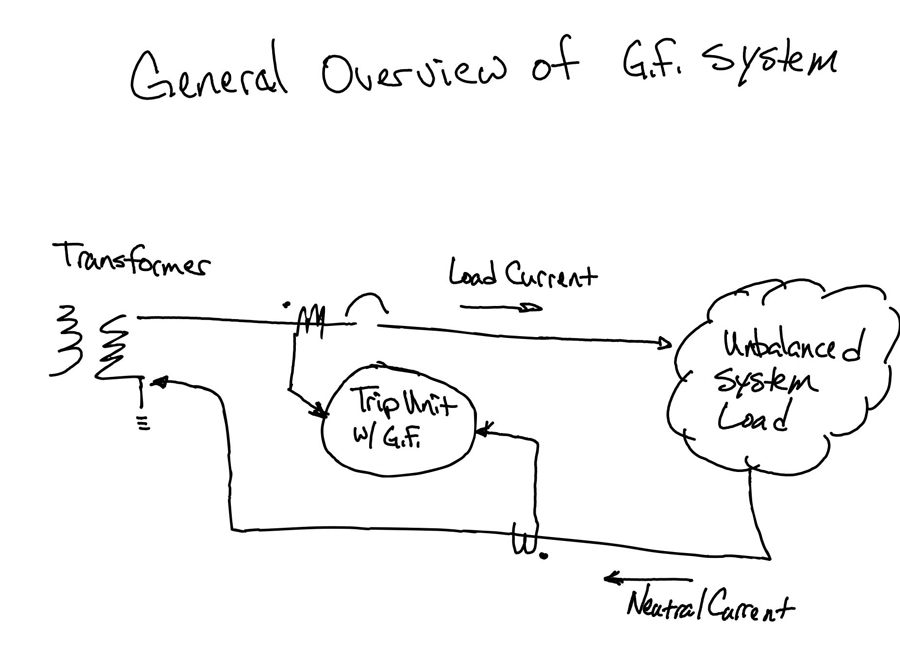
Figure 1: Overview of Ground Fault System
GROUND FAULT PROTECTION FAILURE
Ground fault protection systems come from the factory with several potential error points:
- Incorrect input wiring at the breaker
- Incorrect output wiring of the neutral current transformer (CT)
- Incorrect neutral CT orientation
Ground fault systems have additional potential error points during field installation:
- Incorrect neutral conductor connection to CT orientation
- Neutrals and ground landed together on the same bus in the switchboard or at downstream panels
Assuming that the factory or the contractor installed wiring correctly can lead to issues. These issues typically result in nuisance trips of the breaker that create power outages and production losses. After a system has been energized, a nuisance trip is even more difficult to troubleshoot and correct.
GROUND FAULT PROTECTION TESTING PROCEDURE
Pro-Tip: Trust your testing plan and use good procedures.
- Trip Test: The breaker should operate during this test because it is simulating an unbalanced phase current without neutral CT input to cancel it out.
a. Inject primary current through the breaker to verify ground fault pick-up per manufacturer’s tolerances.
b. Inject approximately 1.5 times the pick-up value to verify that the breaker trips in the published time band for the coordination setting. - No-Trip Test: The breaker should NOT operate because the unbalanced phase current is canceled out by returning the unbalanced current through the neutral CT input.
a. Inject primary current (used in step 1b) through the breaker and return the current through the neutral CT. For this, you will need additional conductors to route the current through the neutral CT.
b. Note that the direction of the current through both the breaker (source to load) and the neutral CT (load to source) should be as shown in Figure 1.
c. If everything is properly installed and wired, the breaker should not trip, as this is a normal current flow situation.
Note on direction of current flow: What is the appropriate direction to return the test current through the neutral CT? Reference Figure 1 again: Neutral current is the normal current that flows on the neutral of an unbalanced three-phase, four-wire system. This current returns from the load(s) through the neutral CT on its way back to the source (transformer).
I had to question my technique when the first of the ground fault protection systems we tested that day failed. After spending some time checking and double-checking, our team moved on to another breaker. To our pleasure, this system worked as we expected it to work.
Given this new piece of validation and information, we:
- Rolled the polarity of the wiring at the CT, even though it matched the wiring of all the other neutral CTs of this type (Figure 2).
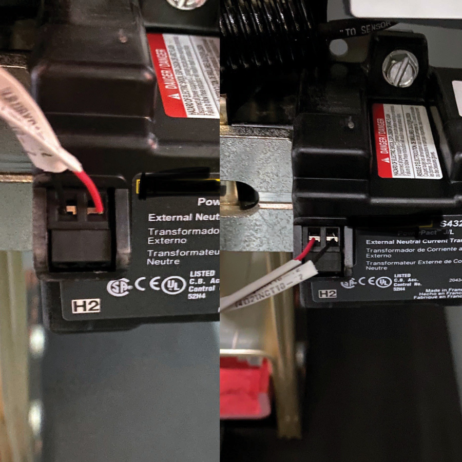
Figure 2: CT Lead with Incorrect Wiring Polarity
- Retested and obtained the no-trip result we expected the first time. While this fixed the operation, the wiring problem was actually at the input to the breaker’s trip unit. As noted earlier, the wiring matched all the other CTs and caused us to question our test procedures.
- This information was passed to the manufacturer to correct the wiring at the breaker to avoid a warranty challenge with our team making a modification.
We continued our testing and found one additional CT wiring issue that was legitimately at the CT (Figure 3). Unlike the first CT issue we identified, this CT had three wires. Following the failed test, we noted that two wires were landed into one connection point of the CT leaving one connection open. After a quick comparison to other similar CTs, we relocated the wire to the proper output, and the issue was corrected, rechecked, and operated as expected.
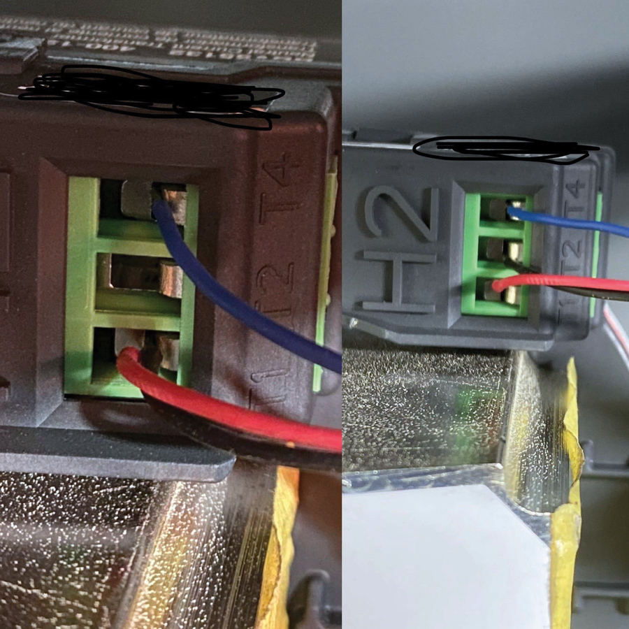
Figure 3: CT wiring is landed incorrectly on the secondary of the CT. On the left, note the empty middle connection. The photo on the right shows the connection corrected with the black wire in the middle connection.
These two big finds helped our customer avoid unnecessary outages in their process. What would have happened if we had not been there to test things that the factory team assumed had been verified at the factory?
IN-SERVICE GROUND FAULT TRIP
Additional complications are possible if a breaker trips on a ground fault event after the system has been in service for many months or even years.
The complication:
- Usually starts with the assumption that the system was properly started up and is working to do its job to protect the equipment from a ground fault event.
- Assumes that the setting is appropriate per the coordination study.
- These assumptions lead to a well-intended facility manager insisting on installing temporary metering in the hopes that you can capture the event. In my experience, the event never seems to occur while the metering equipment is installed. I’m still trying to figure out why that is.
- Many months later, this plan typically leads to another nuisance ground fault protection trip and an outage.
Take the steps necessary to troubleshoot a suspected ground fault trip:
- De-energize the source of power. This typically creates more frustration for the client, who says, “Can’t you do this with the equipment energized?”
- Do a trip test and a no-trip test as described earlier.
- Inspect the installation of the neutral wires. This is particularly important if the CT is mounted on the neutral bus bar.
CASE STUDIES
Following are two case studies related to busbar mounted CTs.
Case 1: A customer experienced repeated ground fault trips that couldn’t be explained.
- The metering didn’t capture anything.
- Our trip and no-trip tests passed.
- Confused and frustrated, I crawled underneath the eight sets of parallel conductors to inspect the neutral CT at the rear of the gear, which was installed against a wall, of course.
- To my surprise, half the neutral wires were landed on one side of the neutral CT and half were landed on the other side (Figure 4). This effectively meant that half of the neutral current flowed through the CT and half did not, which in turn meant that when the conditions were right, enough of the needed neutral current to avoid an operation didn’t flow through the CT.
- It was no easy fix to move all those neutral wires to the correct side of the CT, but after that the unplanned outage calls stopped.
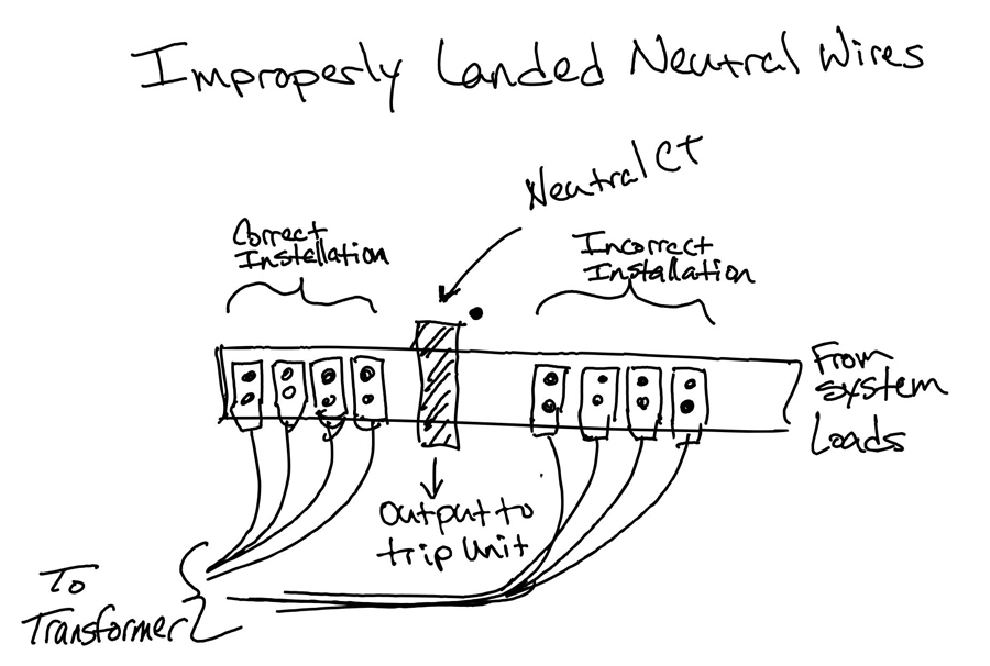
Figure 4: Improperly Landed Neutral Wires
Case 2: A customer experienced a significant ground fault event that the ground fault protection system failed to operate and clear.
- Starting with the basics, we conducted a successful trip and no-trip test — both passed.
- During the inspection of the entire switchboard and neutral wires, it was noted that the installing contractor had landed all the neutrals and all the grounds to the neutral bus.
- By landing the ground conductors on the neutral bus, the contractor effectively defeated the ground fault protection because the ground current from the fault was now passing through the neutral CT.
- When asked why they landed the grounds on the neutral bus, the reply was, “Well, it’s electrically the same point, right?” No. No, it is not. The neutral is a normal current-carrying conductor. The ground conductor only carries current in the event of a fault. Hint: you might see a question like this on the certification exam.
CONCLUSION
When setting up new equipment, we are often the ones charged with ensuring that all known potential failures are checked and corrected if needed. To increase the probability of success, avoid these mistakes or misconceptions technicians make in the field:
- Assuming the neutral CT is a ground CT and the source of current necessary to operate the ground fault protection.
- Passing current only through the neutral CT, which will trip the breaker at the designated pick-up level. However, this is not the intended operational design of the system and therefore provides no value.
- Failing to include the no-trip test in the acceptance testing plan.
Ensuring you understand the purpose of the neutral CT in a ground fault protection system is another step towards meeting the requirements of NETA technician certification.
 Mose Ramieh is Vice President, Business Development at CBS Field Services. A former Navy man, Texas Longhorn, Vlogger, CrossFit enthusiast, and slow-cigar-smoking champion, Mose has been in the electrical testing industry for 24 years. He is a Level IV NETA Technician with an eye for simplicity and utilizing the KISS principle in the execution of acceptance and maintenance testing. Over the years, he has held positions at four companies ranging include field service technician, operations, sales, business development, and company owner. To this day, he claims he is on call 24/7/365 to assist anyone with an electrical challenge. That includes you, so be sure to connect with him on the socials.