

“It’s faster for us to put on the 40-calorie suit to rack breakers out than it is to use the remote racking system,” the customer said — and I wanted to add, “Yes, the remote racking system bought for your safety at a significant investment from your company.” But I did my best to hide my dismay and took the opportunity to inform him of the three factors that determine incident energy in an arc flash:
- Energy: The available fault current at a particular system location
- Time: How long it takes to clear a fault
- Distance: Proximity to the fault, which is exponentially proportional to its intensity
These are the only levers available to reduce an arc flash event’s potential injury to electrical workers.
ENERGY
The first lever for the reduction of available fault current — energy — is the least useful. Facilities are commonly increasing the sizing (ampacity) of their power system
equipment. Low-voltage switchboards of 4,000 to 5,000 amps are becoming increasingly more commonplace. This power is necessary for processes and manufacturing and to save cost over installing multiple smaller systems.
Outside the facility, the utility power system is designed to feed numerous systems (facilities). This translates simply into the idea that there’s plenty of fault current available and there’s just not much that can be done about that, particularly at the service entrance. Arc-resistant switchgear is an attempt to mitigate these high-energy hazards. If you aren’t familiar with arc-resistant switchgear, picture military-tank-like switchgear with plenums (ducts) to route the force of a blast out of the room, thereby mitigating the likelihood of a switchgear explosion injuring a qualified worker.
TIME
The second lever is the time or duration that an overcurrent fault can persist before system protection isolates the overcurrent fault. Traditional power system protective devices are coordinated to obtain a balance between power system reliability and equipment safety (not qualified worker safety). This reliability factor allows overcurrent faults to occur and persist for second(s) while the downstream breakers closest to the fault time out and trip. Please note that each system has its unique coordination settings that determine time delay during a fault.
Fortunately, technology is evolving to provide improved safety for qualified electrical workers and system reliability, creating a win-win for the facility and the qualified worker.
Systems and technology categories to mitigate arc flash:
- Arc-flash relaying
- High-speed bus differential relaying
- Maintenance bypass switching
- Arc-quenching switchgear designs (not addressed in this article)
Systems that (dare I say) can largely eliminate arc flash:
- Gas-insulated switchgear (GIS)
- High-resistance grounding (HRG)
Arc-Flash Relaying
Arc-flash relay technologies work to trip faster than traditional overcurrent protection by using a combination of inputs. The typical inputs are fault current AND light sensors and/or pressure sensors (Figure 1). The sensors consist of fiberoptic point sensors or clear-jacketed fiber loop. Point sensors are typically installed in switchgear compartments (breaker enclosures). Fiber loops can be routed through several sections, such as bus compartments.
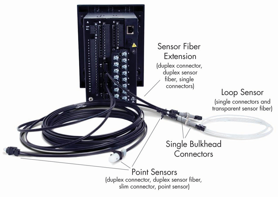
Figure 1: Multilin 350 with Arc-Flash Sensors
Trip and Trip-Faster Testing
These devices add a level of complexity to standard testing. Two tests are required to verify proper operation:
- A traditional overcurrent test would prove that the relay operates per its coordinated settings (time delay).
- The second test would be a combination of both the overcurrent AND a light input.
For the first of these systems I tested, the relay manufacturer recommended a particular camera flash model. I bought that flash and wrote a test plan that would simulate the overcurrent AND initiate the camera flash. To my disappointment (and frustration), the system failed to pass the test. Repeated attempts and double-checks of the camera model didn’t solve our problem. Why didn’t the camera flash work? The time over light (TOL) setting was new to me at that time. Like time overcurrent (TOC), the greater the fault current, the faster the relay operates. In the case of light, the more intense the light, the faster the relay operates (Figure 2).
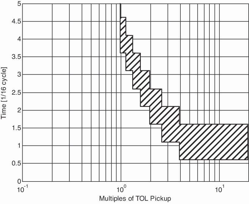
Figure 2: TOL Element Inverse Curve Characteristic
Our solution to verifying this operation was a flashlight. Using a flashlight, we introduced enough light over enough time (a few seconds) to activate the light sensor pick-up element. Once the light sensor element was verified picked up, we initiated our fault current to verify that the relay tripped instantaneously (no intentional delay). Once the trip operation was proven, each loop or point had to be verified. Relays monitor each sensor to ensure that the fiber is intact. A final verification would be to disconnect each sensor individually to ensure that the relay detects this loss and provides notification.
High-Speed Bus Differentials
The waveform in Figure 3 is a fault that was captured by a power system relay. Note the fault that occurs on A phase. Long story made shorter: A worker who was in the wrong cubicle unintentionally grounded an energized 13.8 kV system conductor. Technician note: ALWAYS perform a live-dead-live check of your voltage detection meter. To everyone’s amazement (and good fortune), the only thing that happened was that the facility was plunged into darkness. No explosion, no arc flash, not even a scratch on the grounds. This fault, which was cleared by a high-speed bus differential, demonstrates the value of clearing faults quickly (three cycles in this case).
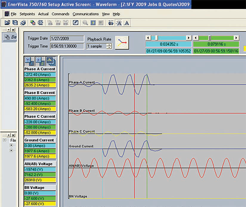
Figure 3: Phase to Ground Fault Waveform
Maintenance Bypass Switches
Clearing faults quickly and at lower current values is the theory of operation behind maintenance bypass switches. As an example, to maintain system reliability, an instantaneous trip on a low-voltage main circuit breaker may be set to 32,000 amps (8 times the rating of a 4,000 amp breaker). This setting is great for reliability, but not for safety.
While racking a breaker in or out in a maintenance situation, the switch is used to turn on an alternate group of settings. In this alternate group of settings, the instantaneous value is changed to a lower setting. This means that instead of 32,000 amps, the breaker could trip instantaneously as low as 6,000 amps (depending on trip unit type). This reduces the amount of fault current necessary to activate the instantaneous element as well as eliminating the time delay to clear a fault, should one occur.
Testing these systems is straightforward. Test the breaker at its normal settings. Place the switch in maintenance mode. Verify the settings group changes. Verify that the breaker operates at the lower current setting. An important final note for power system reliability: Always remember to return the maintenance bypass switch to its normal position (Figure 4).
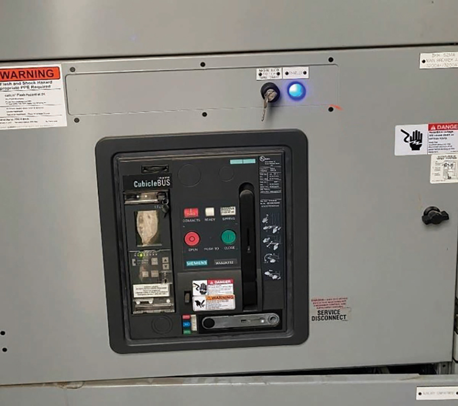
Figure 4: Leaving the maintenance bypass switch enabled reduces power system reliability.
Two brief thoughts on GIS and HRG to eliminate arc-flash hazards:
- GIS gear in a nutshell: No exposed energized parts; no arc-flash hazards.
- HRG: Most (but by no means all) arc-flash events begin as a phase to ground fault. By installing a resistor in the ground circuit, HRG systems eliminate arc flash in these situations by limiting the fault current to as little as 5 amps. Systems provide alarming of a ground fault, and many include methods and components that allow for identification of the faulted circuit.
DISTANCE
Back to my customer and his remote racking system. His statement showed me:
- His safety culture was not walking the talk.
- He wasn’t utilizing NFPA 70E Annex F:
- Eliminate the hazard. For example, use GIS.
- Reduce risk by design. Use HRG systems, arc-flash relaying, and maintenance bypass switches.
- Apply safeguards. Use remote racking and switching to put distance between people and hazards.
- Implement administrative controls. For example, a maintenance bypass switch is most reliably used when added as a specific step in a maintenance procedure to enable the maintenance bypass switch and place in normal when maintenance is complete.
- Use PPE. This is the last line of defense, not the first line.
It may be difficult to alter your system by installing arc-flash relaying or HRG systems. These take money and outage time to reduce the hazards of arc flash and still may not reduce the hazard to an acceptable level.
In contrast to other systems, the use of remote racking and switching is easier to implement. No outages are required, and the training can be done on the job. By modifying how these common system tasks are accomplished, qualified workers can now remove themselves from the arc-flash boundary and still perform their jobs: opening or closing, or racking breakers in or out can be performed outside of the arc-flash boundary or even from another room.
CONCLUSION
In my experience, the customer is right. It is “easier and faster” to use PPE. It can be a pain to learn something new — like walking was faster and easier than learning to ride a bike. However, with a bit of practice, riding a bike becomes second nature, faster, and fun. Remote racking and switching can also become second nature, can be done quickly enough, and keeps you out of the arc-flash boundary, ensuring your future health and safety.
 Mose Ramieh is Vice President, Business Development at CBS Field Services. A former Navy man, Texas Longhorn, Vlogger, CrossFit enthusiast, and slow-cigar-smoking champion, Mose has been in the electrical testing industry for 24 years. He is a Level IV NETA Technician with an eye for simplicity and utilizing the KISS principle in the execution of acceptance and maintenance testing. Over the years, he has held positions at four companies ranging from field service technician, operations, sales, business development, and company owner. To this day, he claims he is on call 24/7/365 to assist anyone with an electrical challenge. That includes you, so be sure to connect with him on the socials.