
Relaying current transformers serve as critical components in the design of a protection scheme. CT performance under fault conditions should be within its operating characteristics for a true representation of fault magnitudes and reliable operation of the protection scheme. To ensure proper installation and operation, CTs are often subjected to one or more tests performed in accordance with standards including IEEE C57.13.1, IEC 60044–1, and IEC 60044–6.
IEEE C57.13.1, Guide for Field Testing of Relaying Current Transformers describes field test methods that assure CTs are connected properly, are of marked ratio and polarity, and are in a condition to perform as designed both initially and after being in service for a period of time. Performing the recommended ratio, polarity, winding resistance, and excitation tests on each tap of a multiple-tap CT can be a labor- and time-intensive job. Combined with substation assets such as transformers and circuit breakers with multiple CTs per phase, it is a complex task to obtain reliable and accurate results.
An excitation test performed using the secondary voltage injection method could require high levels of AC voltage to plot the saturation characteristics and determine the knee point. Special application CTs such as TPY, TPZ, or generator CTs may require thousands of volts to perform this test. This requirement not only makes it a challenging situation in the field environment, but also poses safety concerns for operating personnel.
This conventional method of testing CTs in the field has been used for years with some limitations and drawbacks. With modern advancement in digital processing and solid-state technology, efforts have been made to perform those same tests quickly, safely, and with a high degree of accuracy and reliability.
Alternative Testing Techniques
An excitation test on protection class CTs utilizing nominal frequency 50/60 Hz sinusoidal voltage signal is one of the most challenging tests to perform, as it requires a high voltage/wattage source to drive the CT into saturation to measure its core characteristics. When testing a C800 class CT, test voltage can typically be around 800 V RMS, and for some special cases, 1,300 V may be required to achieve 1 A excitation current for saturation. For some IEC-class CTs, test voltage can easily reach 4,000 V RMS to achieve 1 A saturation.
Many field-portable instruments are unable to deliver that level of AC voltage and wattage. This makes the test difficult to perform for some applications and requires significant safety precautions that must be taken before performing the test. The DC voltage technique can be employed to achieve core saturation and overcome these limitations. IEC 60044-6 Annex B-3 explains the alternate way to perform a CT excitation test.
The flux generated in the core can be represented by
(1)
The integral of voltage over a period of time would be a measure of flux (Φ) produced as shown in equation (1). It can be generated by using AC or DC excitation voltage. The area under the curve reflects the flux produced as shown in Figure 1.
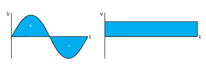
Figure 1: The area under the curve is flux generated using the AC and DC method.
Flux can be increased by utilizing either of the two methods. Either the time period can be kept constant as the voltage is increased, or the voltage can be kept constant with an increase in time. The conventional method used by the industry over the years has been to keep the time period constant (or fixed frequency at 50/60Hz) as the voltage is increased. Alternatively, the DC voltage can be kept the same and the time can be prolonged until the core is saturated. By integrating the constant DC voltage over time, the core saturation can be determined. This saturation can then be mathematically converted back to an equivalent 50 Hz/60 Hz saturation. This will then achieve the same result as the conventional AC excitation test technique.
Figure 2 shows an excitation test result with a knee-point voltage of around 14 kV. The advantage of the DC method is to eliminate the need for higher levels of AC voltage and achieve the same results by utilizing a DC voltage at or below the available line voltage. The technique allows testing CTs with higher knee-point voltages using the same concept with a slightly longer test duration. Additionally, lower levels of DC test voltage allow safer testing conditions and a portable, lightweight instrument ideal for field conditions.
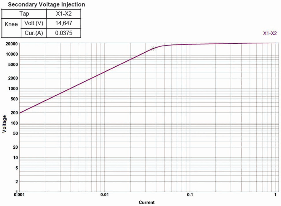
Figure 2: Saturation Test with Knee-Point Voltage around 14 kV
CT demagnetization is an important step to ensure that the core has no residual magnetism. This can be achieved by reducing the hysteresis loops starting from saturation through a series of similar DC excitation reoccurring cycles in opposite directions with progressively reduced magnitudes.
Concurrent Testing Technique
The conventional testing method works on the concept of keeping the primary circuit open, applying an AC voltage to the secondary winding, and measuring secondary voltage/current along with primary voltage values to obtain test parameters such as ratio, polarity, winding resistance, and excitation characteristics curve. For a multi-tap CT, these tests are repeated for each tap either through a manual operation or by utilizing an automatic switching technique.
The concurrent testing technique uses the transformer’s ampere-turn principle to obtain the recommended test results for all the taps and any inter-tap combination simultaneously.
(2)
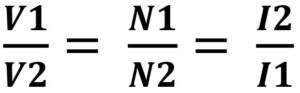
The turns ratio (N2/N1) of a CT is a ratio of the applied voltage on the secondary side to the measured voltage on the primary side as shown in equation (2). The concurrent technique applies the test voltage across the complete secondary winding and measures the voltage across each secondary tap position in addition to the primary winding induced voltage. Concurrent testing test connections to a multi-tap CT can be made as shown in Figure 3.
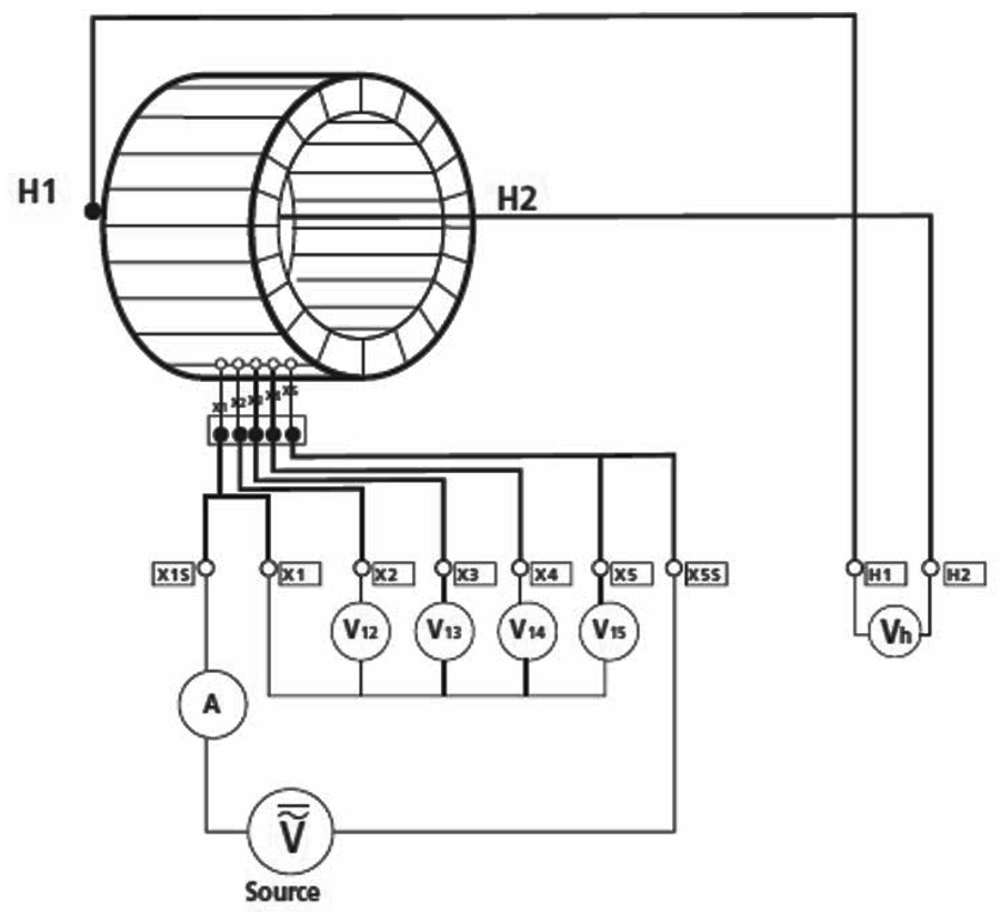
Figure 3: Multi-Tap CT Concurrent Testing Technique Connection Setup
With those measurement values, the ratio for each tap position can be calculated simultaneously as shown in equation 3.
(3)
The excitation characteristics can also be obtained for all the taps by performing an excitation test across the complete secondary winding and measuring voltages across all the taps throughout the test duration. Measured tap voltages along with calculated turns ratios and secondary current can be utilized to plot the excitation curves for all the tap combinations concurrently.
A DC winding resistance test for a CT secondary winding is performed to detect any shorted turns or high-resistance connection point(s) in the CT secondary circuit. The same concurrent technique can be employed to measure the winding resistance of each tap combination by applying a DC current through the entire secondary winding and measuring the voltage drop across each tap position.
Comparative Analysis
This section focuses on the performance characteristics of a CT using two techniques discussed in the previous sections: the DC excitation method and the concurrent test technique. A comparative analysis of test results from excitation tests performed using the AC method and DC method is discussed. The accuracy of testing a multi-tap CT in AC concurrent method is examined by comparing the test results obtained from testing the same CT on a tap-by-tap basis (AC method). Furthermore, the test results from AC concurrent method are compared with the DC concurrent method for accuracy.
AC Excitation vs DC Excitation Test
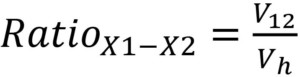
Four types of protection CTs (C400 and C800) with varying saturation characteristics were tested in the field using the AC and DC methods explained in the previous section. The excitation test was conducted between the X1–X5 taps of the CT. Their characteristics are shown in Figure 4 a, b, c, and d.
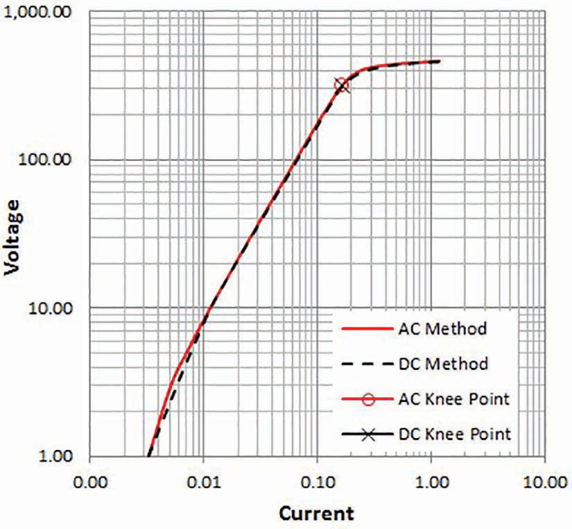
Figure 4a: Comparison of AC and DC Test Method Results
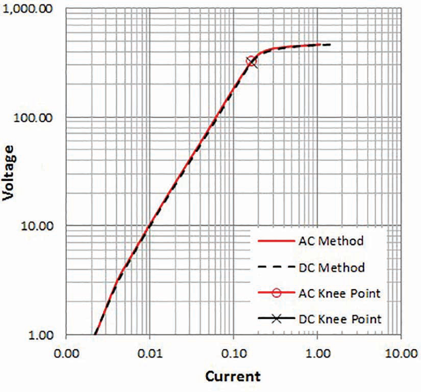
Figure 4b: Comparison of AC and DC Test Method Results
Figure 4c: Comparison of AC and DC Test Method Results
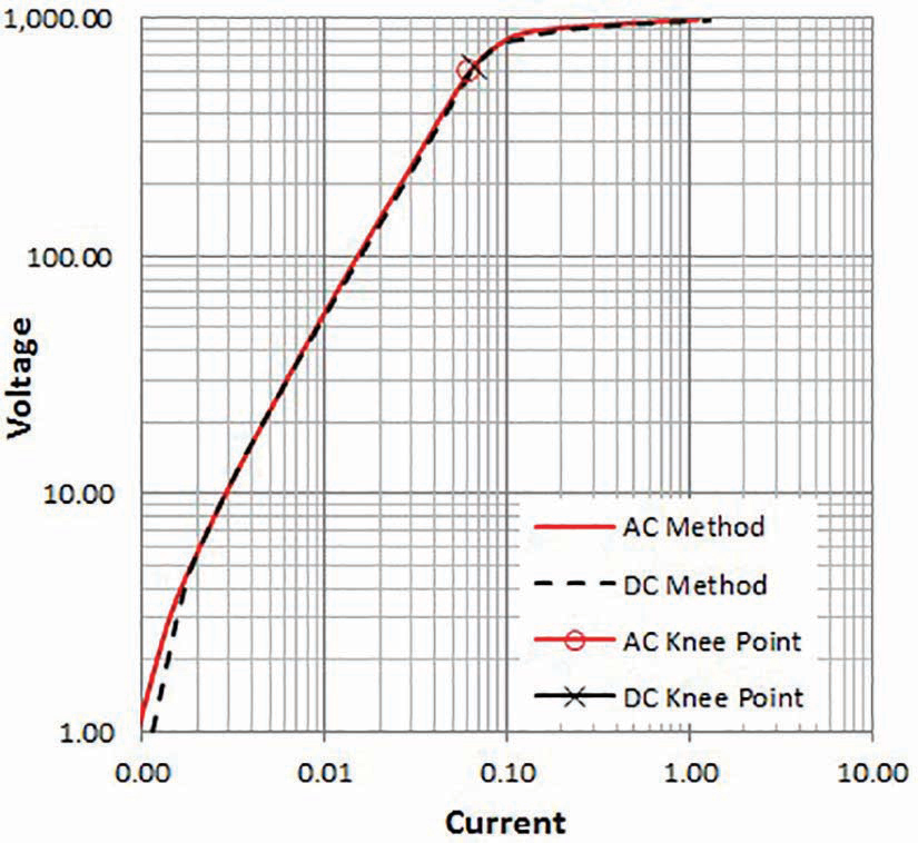
Figure 4d: Comparison of AC and DC Test Method Results
From Figure 4, the saturation curves for two C400 and two C800 CTs obtained from AC and DC excitation methods provided similar excitation characteristics and knee-point values. The difference in knee point measured using the ANSI 45 method (tangent at 45° angle) for the two methods (AC and DC) was found to be negligible.
Concurrent AC vs Non-concurrent AC Test
Excitation Tests. Performing an excitation test using the non-concurrent method involves measuring voltage/current across individual taps. The concurrent method measures the voltage drop across all the taps simultaneously and calculates the secondary current using the ampere-turns principle as given in equation (2). The field results from the AC excitation test across different taps using concurrent and non-concurrent measurement methods are provided in Figure 5. The field results show that the excitation curves using the concurrent measurement method follow the non-concurrent measurements. The results also confirm that the concurrent method could improve testing efficiency by reducing the test time considerably without compromising the accuracy of test results.
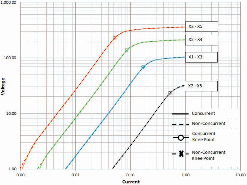
Figure 5: Comparison of Non-Concurrent AC and Concurrent AC Test Method Results
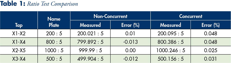
Ratio Test. For concurrent tests, equation (3) can be used to calculate the ratio of each tap by simultaneously measuring the voltage drop across each tap (V12, V23, V34, V45) and the voltage induced on the primary (Vh). Table 1 provides field results of both a non-concurrent and concurrent test across the same taps of a CT. From Table 1, it can be observed that the differences in results between the two methods are negligible.
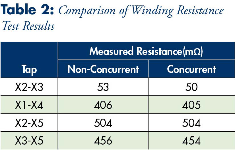
Winding Resistance Test. A DC current is applied to the secondary winding of a CT and the voltage drop across each tap is measured individually. The connections for this test are the same as the ratio test. The winding resistance of different tap positions measured using non-concurrent and concurrent methods is provided in Table 2. The field results show that the resistance values do not differ much between the two methods.
Concurrent DC vs Concurrent AC Test. The concurrent DC method follows the same connection and working procedures of a concurrent AC method. DC voltage is applied across the CT secondary, and the voltage across individual taps is measured simultaneously. The excitation characteristics of a C800-type CT using AC and DC concurrent methods is shown in Figure 6.
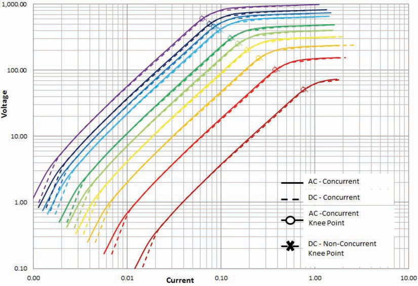
Figure 6: Comparison of Concurrent AC and DC Test Method Results
The linear portions of the AC and DC method excitation curves are observed to be following each other closely. The knee point for CT saturation using the DC method is similar to that for the AC method. The minor differences in the lower part of the curves could be attributed to the non-linear characteristics of CT excitation response in that region and the low-voltage range selection (<5 V) of the instrument during the measurement.
The DC method can be used to test CTs with high saturation points, such as TPY and TPZ that are used in locations where high transient and sub-transient currents are expected. Figure 7 shows the result of a CT with a high knee-point value of close to 14,000 V.
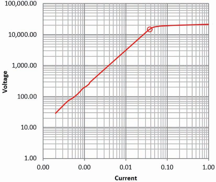
Figure 7: Testing CT with High Knee-Point Using the DC Method
Testing CTs such as TPY and TPZ is very difficult when only the AC method is employed, as the voltage required to saturate the core is high. On the other hand, the DC method only requires a voltage below line power value to achieve core saturation characteristics for these types of CTs.
Conclusion
It is vitally important to test protection class CTs during installation and periodically thereafter to ensure they work as intended for power system protection applications. The tests recommended for CT testing in the industry standards are well established. However, methods used to perform those tests are evolving.
Efforts are being made to create safer operating conditions, test special-application CTs, and improve the efficiency and productivity of the test system through automation, intelligent data processing, and developing smart algorithms utilizing basic principles of transformer operation and electromagnetics.
New measurement techniques proposed in this article, although unique, utilize the concepts well-described in electrical textbooks. DC excitation and the concurrent method of testing offer an alternative approach for testing CTs that provides the same measurements and results as conventional techniques recommended in various international standards. The comparative analysis between different methods indicates that DC excitation and the concurrent method of testing can be utilized in place of AC excitation and individual tap-by-tap testing techniques without compromising the accuracy and reliability of the results. Demagnetization is highly recommended after a DC excitation test to minimize any residual magnetism in the core of the CT.
References
IEC 60044-6, Instrument Transformers Part 6: Requirements for Protective Current Transformers for Transient Performance.
IEEE C57.13.1-2006, Guide for Field Testing of Relaying Current Transformers.
United States Patent: Concurrent Transformer Test System and Method. Patent No. US 9,128,134 B2, Date of Patent: Sep. 8, 2015.
 Dinesh Chhajer manages Megger USA’s Technical Support Group. His responsibilities include providing engineering consultation and recommendations in relation to testing of transformers, batteries, circuit breakers, and other substation assets. Dinesh has presented numerous white papers related to asset maintenance and testing at various conferences within power industry. Dinesh previously worked as an Application Engineer at Megger and a substation and design Engineer at Power Engineers Inc. He is an IEEE member and a licensed Professional Engineer in Texas. Dinesh received his MS in electrical engineering from the University of Texas at Arlington.
 Sughosh Kuber is a Relay and Protection Applications Engineer at Megger North America, where he provides technical support to service companies and utilities responsible for reliable operation of electrical networks. Sughosh brings over 9 years of field experience and academic research in power systems from protection schemes and testing to data analysis for energy efficiency and sustainability. Sughosh received his MS in electrical engineering from New Mexico State University.