
The proven advantages of digital technology for power system protective relays are now commonplace in the power producing and delivery industry. Digital relays provide unsurpassed reliability and extended capabilities at an economical cost. However, keeping pace with the testing and commissioning requirements of these devices has proven to be a challenge for both protective relay engineers and technicians. Although testing procedures have been well-defined for single-function electromechanical (EM) protection devices, modern relay test procedures have been left to the utilities or others to develop, creating possible shortcuts that may compromise the protection system operation.
Extended options and settings, complex trip logic equations, and advanced communication options can lead to overwhelming difficulties in ensuring that a multifunction intelligent electronic device (IED) is properly tested. Observations from within the industry indicate that a common reason for potential errors is the implementation of shortcuts, primarily for simplifying the process and meeting regulatory recordkeeping requirements. Some of these testing shortcut practices include setting and logic changes that accommodate easy testing, creating test values based on single-element settings rather than the actual applications, and failing to test the entire enabled capabilities of the protection system.
This article presents examples of common mistakes typically observed during testing and commissioning, ways to avoid them with simple-to-understand guidelines, and how testing protection systems — rather than single, protective elements — will help avoid protective relay misoperations once in service.
Testing Procedures
The process of testing multifunction digital protective relays brings new challenges for many reasons. First, we must understand the focus of testing these devices compared to testing electromechanical (EM) or single-function relays. The main purpose of testing EM relays was to ensure proper calibration. Calibration and testing procedures were widely available from the manufacturer and relatively easy to understand. Although modern digital technology provides many advantages, finding appropriate guidance for proper testing can be very difficult. This article offers suggestions for simplifying the testing process without compromising proper testing procedures.
Adequate Test Equipment
To properly test multiphase IEDs, it is essential to provide a multiphase source of voltage and current. Testing a multiphase protective element with a single-phase source can lead to false assessment. Some calculations of fault values rely on measured values from a non-faulted phase. Typically, all possible faults should be simulated for each protective element, and all CT and PT inputs must be considered during the testing process. Additionally, all binary inputs and outputs utilized by the IED must be accounted for in the test equipment because it is equally important to test all logic associated with the IED’s operation.
Understanding Different Types of Tests
There are three types of testing procedures:
- Evaluation testing determines whether a protective relay is suitable for use on a particular protection application(s) within a power system. This is also recognized as a process to evaluate and validate the relay manufacturer’s published specifications,
- Commission testing ensures correct functionality of the relay when first installed and activated within the power system.
- Periodic or maintenance testing routinely checks and validates the correct operation of an already installed and active protective relay.
For the purposes of this article, we refer mainly to the commissioning of digital protective relays, although the discussion can also be relevant to the other testing processes.
First Process: Why Do We Test?
For EM technology, the main purpose of testing was to ensure proper calibration of the device. Over long periods of time, contacts, springs, potentiometers, and coils tend to require recalibration, cleaning, or adjustments to ensure proper operation. The term silent sentinel was often used to describe this type of technology because no self-diagnostics were present to determine whether or not the relay would function properly in the event of a fault. With no such calibration required for digital technology, as well as the ability to rely on certain self-diagnostics, why is the commission process still required?
In 2013, the North American Electric Reliability Corporation (NERC) released a report that claimed a dramatic rise in the annual number of misoperations due, in large part, to the complexity of programming and testing digital protection relays.
As shown in Figure 1, misoperations primarily occurred due to:
- Incorrect setting/logic/design errors
- Communication failures
- Relay failure or malfunctions
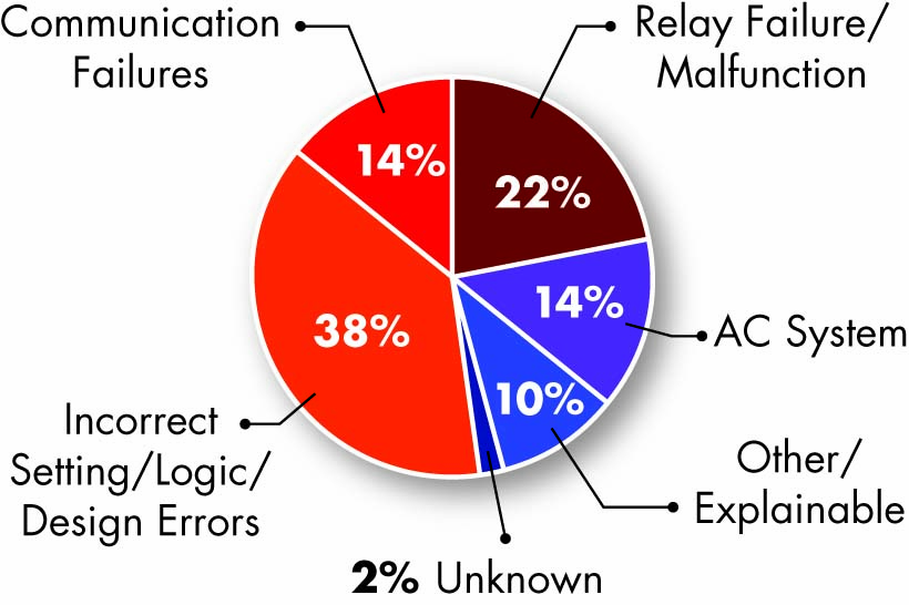
Figure 1: 2012 NERC Misoperations Graph
These events include human error during testing and maintenance activities. This human error, resulting in improper protection system activation, has contributed to large disturbance events.
Proper testing is just as important for multifunction digital IEDs as it is for older EM technology, but the focus has changed significantly. It is true that IED self-diagnostics can alert operations of an internal failure and remove itself from service, but only proper testing procedures can determine whether the protection system is properly configured.
Complex logic configurations, multiple setting groups, communication-based protection schemes, and a large number of protective elements in a single IED add significant challenges to proper commissioning. Much of this complexity has led to recognized shortcuts within the testing process, which can ultimately lead to misoperation.
Second Process:
What Do We Test?
At first glance, this may appear to be a simple question, but when faced with the complexity of a modern protection IED, it is anything but. The components tested are as follows:
- Protection elements. Each active protection element must be tested to ensure it has been set properly. This may seem unnecessary because there is no calibration, but relay engineers and technicians are quite capable of human error in setting each device. A misplaced decimal point, a forgotten time delay, or even forgetting to enable an element are all possible and can lead to misoperations.
- Associated logic. This important factor is often overlooked. The complexity associated with some logic equations adds to a large majority of misoperations. For example, when protective element supervision from a breaker contact is required, breaker simulation during the testing process is essential. Many protection IEDs also have programmable human–machine interface controls, some of which invoke safety-related commands such as hot line tag (Figure 2). If the controls are not programmed and tested properly, extreme hazards could be present.
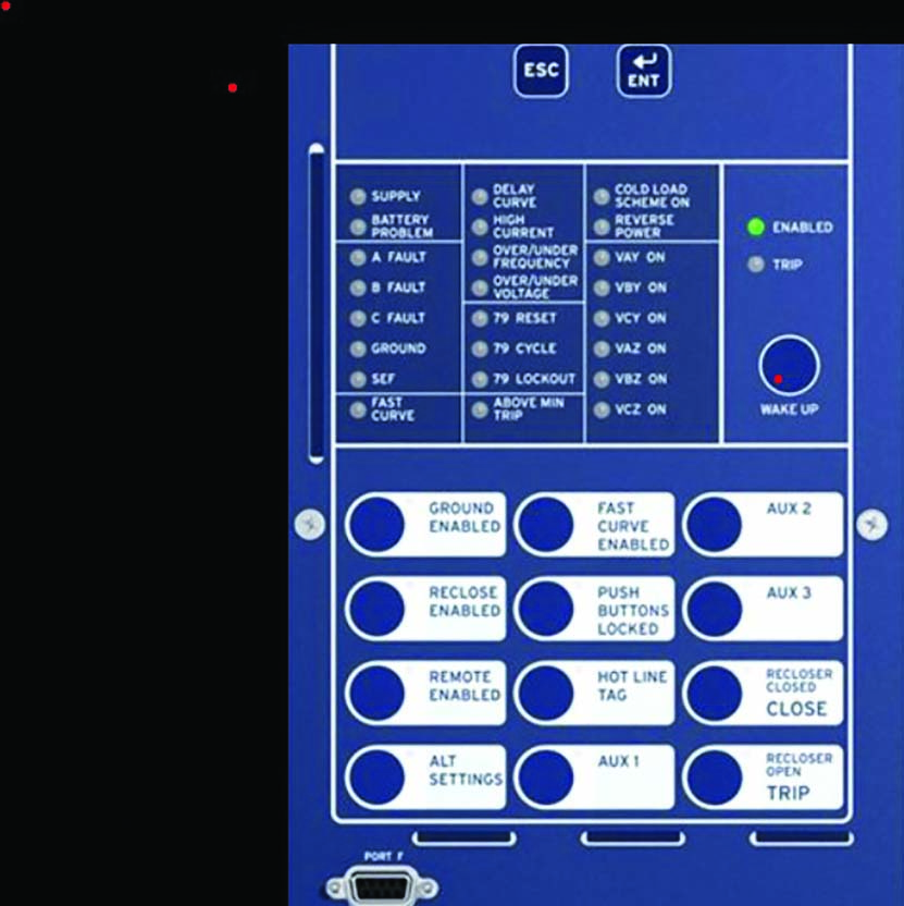
Figure 2: Feeder Relay with Human–Machine Interface Control
- Communication-based protection schemes. These are most often seen in transmission line protection. In the majority of cases, they are the basis for end-to-end testing. However, these types of tests are time-consuming and often difficult to complete. Nonetheless, this critical test for a transmission line enables the protection engineer to verify the delay time of the teleprotection signals (i.e., the delay time between sending signal transmissions recorded on the first end and the received signal recorded on the other end) immediately after executing the shot, as shown in Figure 3.
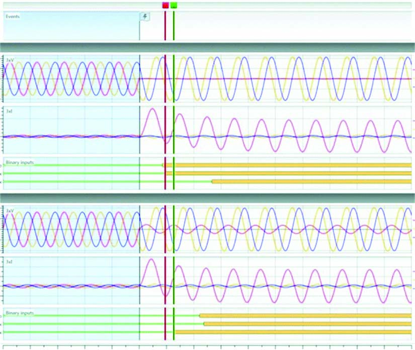
Figure 3: Delay Time of Teleprotection Signals
Third Process: How Do We Test?
These test procedures should be avoided:
- Testing a protection IED based on factory settings
- Changing, altering, or disabling the associated logic with each protective element to validate settings
- Changing, altering, or disabling the components of a protective element to validate settings
- Testing the IED by relying only on the settings that lie within the relay
- Closing the relay trip circuit without the metering validation of a non-trip state
These procedures should be followed:
- Ensure the settings coincide with those pertaining to the application and not factory or predefined test settings.
- Test the device with associated logic enabled, considering both sides of a logic equation for proper validation.
- Test the element without changing settings such as pick up, dropout, or time delays and using proper fault values for fault simulations.
- Use relay software to validate proper secondary CT and PT wiring prior to enabling the trip circuit (Figure 4).
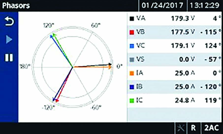
Figure 4: Relay-Metering Software
The proper test sequences that account for associated logic are:
- Begin each test with a proper pre-fault condition: Be the relay. This should include, but not be limited to, the proper simulation of breaker contacts and the application of pre-fault analog values (nominal) that are maintained long enough for lockouts to reset (feeder management relays). Doing so will mitigate logic interference such as switching onto fault, cold load pickup, and so on.
- Maintain a proper calculated fault value until the element picks up, allowing for the validation of trip times and thresholds.
- Follow up with a proper post-fault state, including breaker open logic and faulted values that would be eliminated in a normal trip-state condition. Doing so removes interference from associated breaker failure conditions.
- Ensure that calculated test values coincide with published tolerances provided by the relay manufacturer. Most modern testing software allows for automated test sequences and assessment (Figure 5).
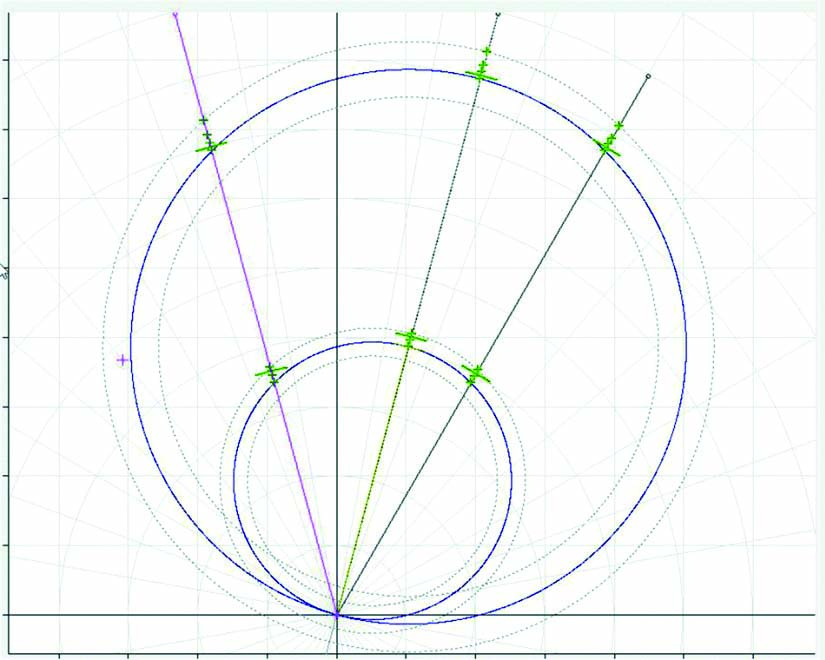
Figure 5: Automated Tests from a Test Set
Fourth Process:
When Do We Test?
The NERC Planning Committee’s System Protection and Controls Task Force publishes maximum testing intervals by equipment category (Figure 6).
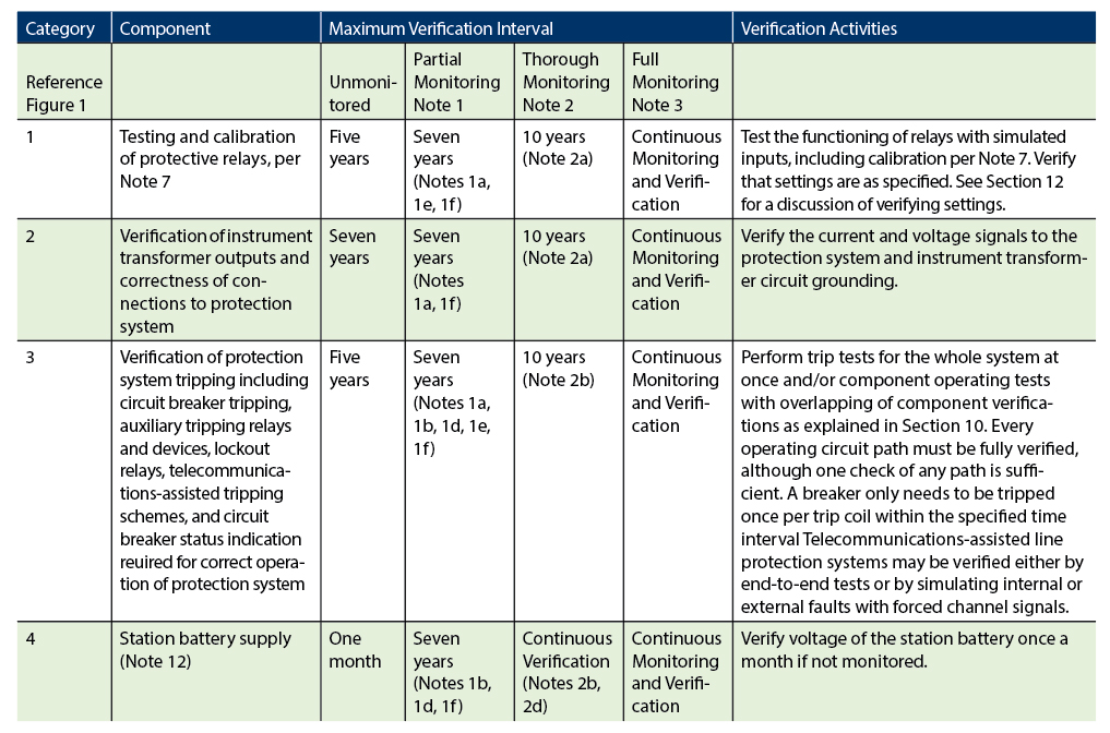
Figure 6: NERC Testing Intervals
Figure 7 illustrates published recommendations for relay testing intervals according to InterNational Electrical Testing Association (NETA) standards.
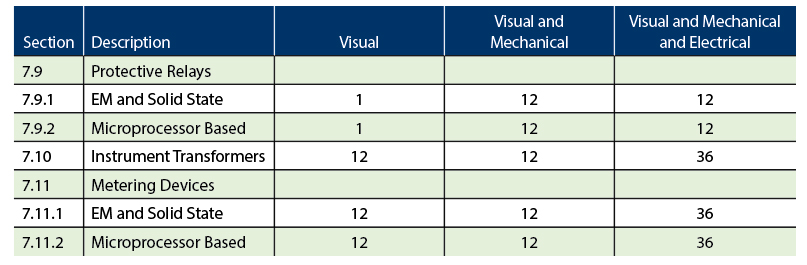
Figure 7: Relay Testing Intervals per NETA (Months)
Additional considerations for testing intervals:
- Environmental conditions
- Criticality of the protected asset
- Redundancy of protection
- Historical performance.
The final considerations for when to test:
- Setting changes after commissioning
- Relaying firmware updates
- Rewiring in the trip circuit or secondary CTs or PTs.
Conclusion
When considering digital protection relays, it is important to understand the impact that self-diagnostics play in the testing process. Although self-diagnostics will detect the failures of certain components, such as power supplies, microprocessors, and circuit board parts, we must also understand what it will not detect, such as relay output contacts. Most important, self-diagnostics will not alarm when there is human error in setting the protective elements or logic. While digital technology adds greater reliability within the protection system, this does not eliminate the need for proper testing. Rather, this technology necessitates refocusing the testing process.
References
D. Welton. “Avoiding Potentially Dangerous Testing Practices for Digital Relays,” Proceedings, Georgia Tech Protective Relay Conference, pp. 1-4, 2008.
D. Welton, “Testing Advanced Digital Relay Systems,” Electric Energy Magazine, May/June 2004.
F. Steinhauser. “Network Simulation on the PC — New Options for Protection Testing,” Proceedings, IPTS, 2004.
North American Electric Reliability Corporation (NERC). Protection System Maintenance: A Technical Reference, 2007 [online]. Available at https://www.nerc.com/pa/RAPA/PA/Performance%20Analysis%20DL/NERC_2018_SOR_06202018_Final.pdf.
 Drew Welton is Vice President of Sales for intellirent, a division of Electrorent. He provides strategic leadership to the sales team and creates new business development for the industrial testing and power producing industries. Drew was previously the North American Regional Manager for OMICRON, a Regional Sales Manager with Beckwith Electric, and National Sales Director for Substation Automation with AREVA T&D. He has written numerous articles on substation maintenance testing and has conducted training sessions for substation technicians and engineers at utilities and universities across North America. He is a 20-year Senior Member of IEEE-PES, IAS, and an active member of the Transformers Committee. He has been a contributor on a number of PSRC working groups and presented at many industry conferences specific to power-system protection and control. He holds a BS in business administration from Fort Lewis College in Durango, Colorado.