
In the early days of protective relaying, it was recognized that communications between substations could improve relaying performance. Schemes such as power line telephony (1920s) and pilot wire relaying (1930s) evolved into digital time division multiplexers (TDMs) (invented in 1960s and used for power system communications in 1970s). TDM allowed audio teleprotection, audio-based relaying, SCADA, and telephony to share a single link from substation to substation. In the late 1970s, T1 channels could be leased from the phone company, but that was not ideal. Fiber optic communications became viable in the 1980s and began to be deployed in substations in the late 1980s. Over the past 35 years, the use of fiber optics in substations has exploded for both inter-substation and intra-substation purposes.
WHY DO WE NEED COMMUNICATIONS IN A SUBSTATION?
In the beginning, there were fuses, and it was good. Fuses developed into overcurrent relays and circuit breakers. Once the power grid became a mesh, selectivity (disconnecting only the faulted section of a transmission line) became more important — and more difficult. The individual faulted line had to be isolated, and that meant communications were needed. Pilot wire relaying worked on a principle similar to a garden hose: Water (current) into one end had to equal water (current) out the other end, or there was a leak (fault). To make this determination, you needed information from the far end of the line, hence communications of some sort. Even if you could make a decision based on the information at one end (impedance relaying), you had to instruct the breaker at the far end to open (direct transfer tripping).
Beyond relaying, there is a need for voice channels, metering data, SCADA data, and with intelligent electronic devices (IEDs), a plethora of data communications. Like everywhere else, the advent of Ethernet has caused an explosion of data traffic between substations and control rooms.
EARLY SUBSTATION COMMUNICATIONS
The first substation-to-substation communications were continuous wires carrying DC (transfer trip signals), AC (pilot wire relaying), and analog audio for voice and SCADA. This was okay but limited by cable impedance and noise to relatively short lines. Various techniques like audio tone teleprotection and power line carrier extended distances but were still limited in their application.
Telephone company communications channels could work over very long distances but providing them into a substation was costly, and inherent reliability and time delay issues made them less than ideal. The utility practice of not trusting the phone company for relaying unless absolutely necessary also limited its use.
Telephone systems were based on the principle of putting many different channels on one pair of wires. Early analog systems used frequency division multiplexing (FDM), and digital systems used time division multiplexing (TDM) in the 1960s. Deployed in a substation, a multiplexer could provide all the various types of communications with just two pairs of wires, and all the equipment could be owned by the utility. This was very close to a good solution, but wires between substations were still not an ideal solution.
WHY FIBER?
The limitations of copper-wired systems could be overcome with optical fiber systems. Optical fibers could go very long distances and were immune to ground potential rise, were virtually noise-free, and had very low latency. Direct relay-to-relay fiber systems were developed, but using a pair of fibers for only one relaying channel is grossly inefficient. In the 1980s, this gave rise to substation-grade digital fiber multiplexers. Using T1 TDM at 1.544 Mb/s, 24 channels could be telephone, audio four-wire, synchronous data at 56/64 kb/s, or 19.2 kb/s asynchronous data. This was plenty for point-to-point communication between the substations at the time. Latency was low (~1 ms) and consistent, allowing differential relaying to be deployed using 64 kb/s synchronous channels. The major relay manufacturers offered RS-449 and G.703 interfaces that were designed for these channels.
Early Fiber Multiplexers
As time went on, these substation-specific multiplexers added channels and features such as built-in transfer trip modules and short-haul fiber interfaces for direct connection to relays. They were built to the C37.90.x standards for operation in the substation environment.
One limitation was that if a fiber was broken, all communication between substations was lost. This challenge required a backup system with alternate fiber paths, adding considerable complexity and cost. RFL Electronics, Inc. pioneered a self-healing fiber optic T1 ring that would reroute traffic in under 1 ms when a fiber was lost. This eliminated the last reason not to use fiber between substations.
Modern Fiber Systems
While T1 self-healing fiber rings are still deployed in thousands of applications, the bandwidth is limited to 1.544 Mb/s, which is very slow by today’s standards. For a time, hardened telecoms-grade synchronous optical NETwork (SONET) multiplexers running at 155 Mb/s or higher provided all the needed bandwidth, but these were expensive devices adapted from telephone suppliers and were challenging to configure. The evolution of Ethernet over fiber allowed simpler network protocols to be adopted.
The ubiquitous Ethernet protocol allows easy communications by many devices over a single channel, which can be carried over fiber between substations. It is easy to deploy and inexpensive and works great for SCADA and IED traffic.
Unfortunately, standard Ethernet is not ideal for relaying for the following reasons:
- Communication delays vary based on traffic loading.
- Equipment is usually office grade and therefore not suitable for the substation environment.
- Typical IED interfaces like telephone, RS449, RS232, transfer trip, etc., are not available in typical Ethernet equipment.
- Self-healing rings can be formed but recovery from failures can take seconds.
- Testing the operation under one network loading condition does not ensure that the system will work under all loading conditions. This terrifies protection engineers.
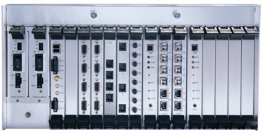
Many of these limitations have been overcome by the development of substation-specific devices for intra-substation and inter-substation communications. These continue to advance, and protocols such as MPLS multi-protocol label switching (MPLS) are even more suited to substation applications. Figure 1 shows the back of a modern packet-switched multiplexer with several channels.
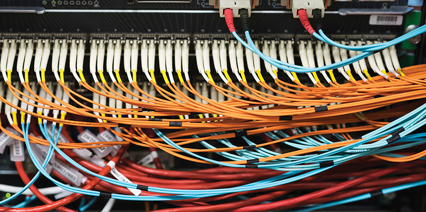
INTRA-SUBSTATION FIBER
Within a substation, three typical fiber communications provide numerous benefits such as limitless bandwidth, noise immunity, elimination of ground potential rise issues, and simpler connections.
IEEE/ANSI C37.94
As described above, at one time, many relay manufacturers offered direct fiber point-to-point systems. They also offered short-haul versions with a fiber service unit that would convert the fiber back to electrical signals for long-haul communications over a multiplexer.
While this worked, it was cumbersome to connect a fiber to a box that needed power and a short cable to a multiplexer. It would have been helpful to have a universal protocol that allowed you to plug a fiber from any relay into any multiplexer — plug and play! After a bit of bickering, the multiplexer and relay manufacturers agreed to a short-haul protocol designed specifically for plug-and-play connections at 56 kb/s — 1.5 mb/s between relays and multiplexers. In 2002, IEEE/ANSI C37.94 was approved.
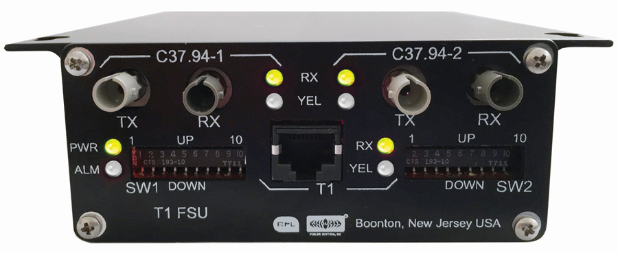
This standard took advantage of the huge bandwidth in short-haul multimode fiber, inexpensive sugar-cube fiber transmitter/receiver pairs, and pre-terminated fiber jumpers. It was very quickly adopted by a variety of vendors and has been proven to solve that problem. It was the prevalent use of fibers in EHV substations until IEC 61850 came into its own. Figure 2 shows a C37.94 to T1 converter.
IEC 61850
No discussion of substation fiber would be complete without a bit of talk about IEC 61850. Numerous tomes have been written to describe this easy-to-use standard, and any detailed description is well beyond the space allotted for this article. More than 20 years ago, the IEEE PES PSRC and PSCC began an effort to consolidate all communications and tripping functions over a substation LAN. This initiative, called the utility communication architecture (UCA), was mirrored by a European initiative called IEC 61850. Eventually, the efforts were merged.
The goal of the new protocol was to remove all copper wiring for user interfacing, tripping, analog signals, etc., from a substation relay room. The cost and complexity of wiring all the intelligent devices would be eliminated and replaced with a redundant high-speed fiber Ethernet network with connection to all devices. The complexity would be built into the device software, and on-the-fly reconfiguration of tripping logic based on conditions would be possible. The complexity proved to be daunting, and IEC 61850 continues to roll out more slowly than hoped, but it is gaining acceptance.
Ethernet Over Fiber
Nearly all intelligent devices in a substation now have Ethernet ports for configuration, control, oscillography, and sequence of events. The days of RS232 ports plugged into a laptop have largely been replaced with an Ethernet cable plugged into a switch. It is inherently simpler for a technician to plug his laptop into a switch and have access to all the devices in the substation, even if it’s not running IEC 61850. Banks of Ethernet switches can connect hundreds of devices to a single laptop.
With devices all over a substation connecting to a central switch, the cabling becomes bulky and expensive. Replacing Ethernet cables with fiber cables can be less costly and is certainly less bulky.
OPTICAL FIBERS
One aspect of fiber communications is its capability for much higher bandwidth and greater distances than substations require. As such, the typical substation application is relatively simple and straightforward compared to telecommunications applications.
- Optical fibers are designed to work in multimode (MM) or single mode (SM). The mode refers to how light reflects and refracts in the fiber and can have an impact on very-high data rates over long distances. Multimode fibers can be 62.5 µm or 50 µm in diameter; single-mode fibers are 9 µm. From a user perspective, all you need to know is which type of interface the equipment has and deploy matching fibers.
- Users must be careful not to mismatch fiber types. A multimode fiber connected to a single-mode patch cord will lose nearly all of its power due to the differences in diameter.
- As can be seen in the Table 1 on page 8, multimode fibers also have significantly higher loss per kilometer. As a rule of thumb, multimode fiber is only used in intra-station applications. The heads for multimode are usually less expensive. Fiber patch cords for multimode are usually orange and single mode are yellow, but this is not always the case.
FIBER TRANSMITTERS
- Fiber transmitter power obviously controls how far you can go. Fiber transmitters have conventional LEDs or laser diodes; the lasers have much more launch power.
- Lasers for substation equipment are typically under 1 mW for eye safety reasons but be sure to check the output power before staring into the transmitter.
- Optical wavelengths are 850 nm (red), 1300, and 1550 nm (infrared).
- Fiber optic transmitter output power varies considerably over temperature, so a safety margin of 3 dB must be taken into account when engineering or testing fiber systems.
FIBER OPTIC CONNECTORS
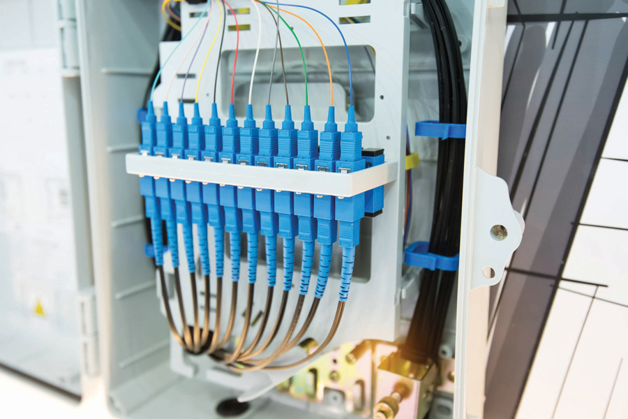
Fiber has many advantages over copper cables, but the connection points can be daunting. Inter-substation fibers are typically terminated into a junction box often called a patch panel. This is required because the raw fibers come in big spools and the connectors have to be installed once the fiber is run. This is a skilled job that is usually left to certified installers. Once landed at the patch panel, connections are made from the panel to substation devices via jumpers that can be purchased in any length so the technician does not have to be skilled in optical fiber termination.
Fiber jumpers (also called patch cords) usually have two fibers: one for transmit and one for receive. If they are terminated in individual simplex connectors, it is up to the installer to connect the correct fiber to transmit or receive as required. Some connectors are duplex, containing both fibers in one connector. Convention is that patch cords are rolled from end to end so proper connections are maintained. Figure 3 shows a typical patch panel with the bare fiber from the remote station at the top and fiber patch cords at the bottom.
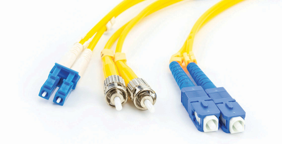
The main fiber connectors used in substations are ST and LC. The SC connector is also used occasionally.
- ST is a simplex connector with a bayonet-type retention. It comes in metal and plastic. It has been around for over 30 years. C37.94 specifically calls out ST connectors.
- LC is a smaller connector with a push lock retention. It is very common in Ethernet network equipment. It is available in simplex and duplex configurations.
- SC is a square plastic push-pull connector. It has largely been replaced by LC, which is half the size and more secure once connected.
Figure 4 shows fiber connectors LC, ST, and SC.
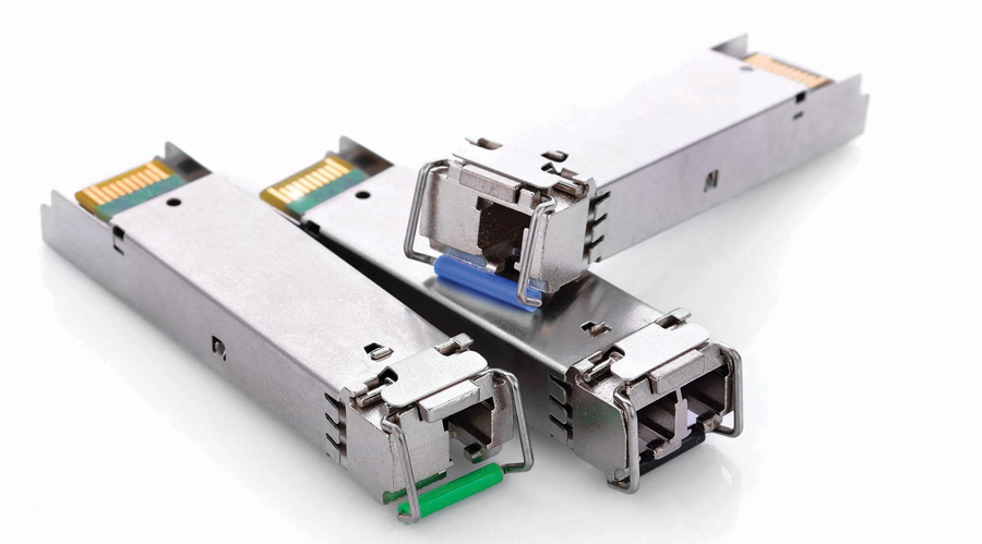
A small form-factor pluggable (SFP) device is not a connector but an electrical plug-in module that can provide an LC fiber port. It is available in many wavelengths, distances, and speeds. Modules also have various levels of diagnostics. It is important to confirm which SFP heads are supported by the manufacturer. SFP heads are typically inexpensive and allow easy upgrades to higher speeds or longer distances if required. This type of head is most commonly used on networking equipment. Figure 5 shows simplex and duplex LC SFP heads.
OPTICAL POWER BUDGETS
The controlling factor in substation optical communications is usually the power budget. The bandwidth of most anything in a substation is so low compared to the limits of fiber optics that the only real question is, “Do I have enough power to get there?” Canned intra-substation systems for short distances will often make it simple by giving the maximum length of a given type of fiber. It’s good to know how the budgets are built so you can build your own.
In principle, it’s quite simple: The transmit power, minus the loss in the media, must exceed the minimum sensitivity of the receiver. There are a few complications, but that’s essentially it.
To calculate the power budget, you need to know the loss per kilometer of fiber, loss per connector, and loss per splice. You will, of course, also need to know the length of the fiber, the number of connectors, and the number of splices. Table 1 shows the values most commonly used for budget calculations.
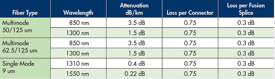
These are very conservative numbers from EIA/TIA 568. Real-world numbers are typically lower.
Let’s do a sample calculation for inter-station fiber 15 km long. We’ll use single-mode 1310 nm fiber, which is very common for longer runs.
Fiber loss (15 x 0.4) = 6 dB
Splice loss (4 x 0.3) = 1.2 dB
Connector loss (2 x 0.75) = 1.5 dB
Total Loss = 8.7 dB
Add in a safety margin = 3 dB
Power budget = 11.7 dB
This means the transmitter must put out at least 11.7 dB more power than the minimum sensitivity of the receiver. Transmitter/receiver pairs are specified with a minimum budget or transmit and receive levels. If you are given a budget, you are good to go as long as it’s greater than 11.7. If you are only given levels, do the following:
Minimum transmitter level = -9 dBm
Minus power budget = 11.7 dB
Minimum sensitivity of RX = -20.7 dBm
If the receiver is rated at -20.7 dBm or lower, this will work. From this, you can see that 850 nm multimode fiber over the same link would have a power budget of 55 dB, which cannot be achieved. This is why single-mode fibers are typically used inter-station and multimode fibers are used intra-station. The commonly provided maximum distance on multimode heads is 2 km.
The most common source of confusion when working with power calculations is average versus peak power. Digital fiber optic communications can use direct modulation (on/off equals 1/0) or more complex methods such as phase shift keying where the relative phase of a carrier denotes 1s or 0s. Regardless, protocols are designed to provide lots of on/off transitions to provide easy clock recovery and therefore tend to have the transmitter on about the same amount of time as it’s off. This means that if you measure the average level, it will be one-half or 3 dB lower than the peak level.
It’s important to know that your transmitting device is outputting a normal protocol and how your light meter works. Some light meters measure average, some peak, and some are selectable. It’s also important to know the minimum and maximum sensitivity of your receiver. Transmitter and receiver device ratings are typically listed in peak, but most measuring devices will read average.
You also must not apply more signal to a receiver than its maximum or you risk distorting the pulses and getting bit errors. It is not as common today, but older devices designed for high sensitivity would have lower maximum input levels. Intra-station fiber applications are typically not a problem. If you have a high-power transmitter and a high-sensitivity receiver designed to work over 100 miles of fiber, they might not work with a 2-meter patch cord on the bench. This can cause real headaches when bench-testing a system before deployment. Physical attenuators may be necessary for short-range work.
FIBER HANDLING
One area where copper cables outperform fiber optics is ruggedness. It’s easier to damage fiber than cable. At its heart, the optical fiber is a piece of glass from termination to termination. Break that glass and you have very high losses. There is gentle cladding around the fibers to ruggedize them beyond bare glass, but they are still subject to breakage. Some of the things to keep in mind:
- Gentle bends. Do not do right-angle bends. Keep the minimum radius to 10x the cable radius (1–2” is typically safe).
- No tie-wrap guns. Whatever you do, don’t decide to neaten things up by tie-wrapping everything down nice and tight. Fiber should be loosely constrained and kept from being pinched when doors are moved.
- Dirt and dust. The terminations are a fragile point. The flat optical surface must be kept free of dirt, dust, and scratches. It is best practice to reinstall caps on fiber patch cords and into tx/rx connectors immediately upon removing the fiber.

FIBER TESTING
Fortunately, several tools are available for testing fiber optic power.
Power Level
Maintaining an adequate power level at the receiver is important for reliable operation. Any defects or damage in the fiber can greatly affect the received level. Fortunately, testing fiber optic power is quite easy. By selecting a standard meter with the correct wavelength, connector, and detector diameter, you can merely read off the received level. Most meters today use large-diameter detectors so that isn’t usually an issue.
As in the power budget calculations, pay attention to peak versus average levels. If you find a low level at the receiving end, you need to go to the transmitter with a short patch cord and measure its output. That will tell you if the problem lies in the transmitter or the fiber.
Optical Time Domain Reflectometer (OTDR)
Once you’ve determined that the transmitter is outputting the proper level but insufficient power is coming out to the receiver, you know the fiber has a flaw. The trick is how to find it. For short lengths of fiber, it’s usually easier to just run a new fiber. For longer runs across substations or out into the switchyard, it might be worth finding the problem and splicing the fiber. The tool you need is an optical time domain reflectometer (OTDR). This is a handheld device that is fairly easy to use. It will send a pulse of light down the fiber and time how long it takes to find any reflections. A change in the fiber characteristic (typically a crack or the end of the fiber) will cause a reflection. Since light travels through fiber at a known speed, about 200 meters/microsecond, the device can calculate the distance to the feature causing the first reflection. Tracing out the fiber will often point to an obvious flaw (tie wraps are the usual suspect).
Bit Error Rate Testing
Now that we know we have enough, but not too much, power reaching the receiver, the communications should work flawlessly. If it doesn’t, you are pretty much at the mercy of the connected equipment to tell you why not. The problems at this point are unique to the equipment — it could be settings, protocols, timing, etc. Communications statistics and diagnostics are almost always built into the end equipment. Look for bit error rate values in the user interface. They should be virtually zero, and anything above 1 bit error per 1 million bits (BER=1e-6) is pretty bad. Minimum acceptable rates are typically 1 bit error per billion bits (BER=1e-9).
Ring Failover
It is also important to test what happens in a failover. If there are redundant communications and one path fails, do the communications recover in the specified time? In addition, you should ensure that the system recovers from various failures around the ring. When doing various breaks, you must allow adequate time between failures per the manufacturer. It’s good to set up a communication path on a self-healing ring, randomly yank out and reinstall fibers, and then check to see that communications remain intact.
Some equipment like the T1 fiber ring can recover in less than 1 ms. Very specialized systems can perform what is known as hitless switching where there is no loss of communications at all during fiber breaks. The other end of the scale is spanning tree protocol (STP), which is the protocol used by ordinary Ethernet. STP can also be configured in a ring as well, and it will recover from fiber failures, but it can take up to 30 seconds.
SUMMARY
Using fiber for substation communications is here to stay, and everyone working on relays and communications equipment should be versed in it. The good news is that fiber is more reliable than many other communications channels and once you understand it, easier to work on.

William G. Higinbotham has been president of EA Technology LLC since 2013. His responsibilities involve general management of the company, including EA Technology activities in North and South America. William is also responsible for sales, service, support, and training on partial discharge instruments and condition-based asset management. He is the author or co-author of several industry papers. Previously, William was Vice President of RFL Electronics Inc.’s Research and Development Engineering Group, where his responsibilities included new product development, manufacturing engineering, and technical support. He is an IEEE Senior Member and is active in the IEEE Power Systems Relaying Committee. He has co-authored a number of IEEE standards in the field of power system protection and communication and holds one patent in this area. William received a BS in computer/electrical engineering from Rutgers, the State University of New Jersey’s School of Engineering, and worked in the biomedical engineering field for five years prior to joining RFL.
Some images courtesy of Hubbell Power Systems, Inc., a Hubbell Inc. company.