

Grounding transformers are most frequently — but not exclusively — used in the renewable industry to provide a relatively low-impedance path to ground in case of surges. This allows for safe maintenance of the grid without fear of damaging the electrical infrastructure.
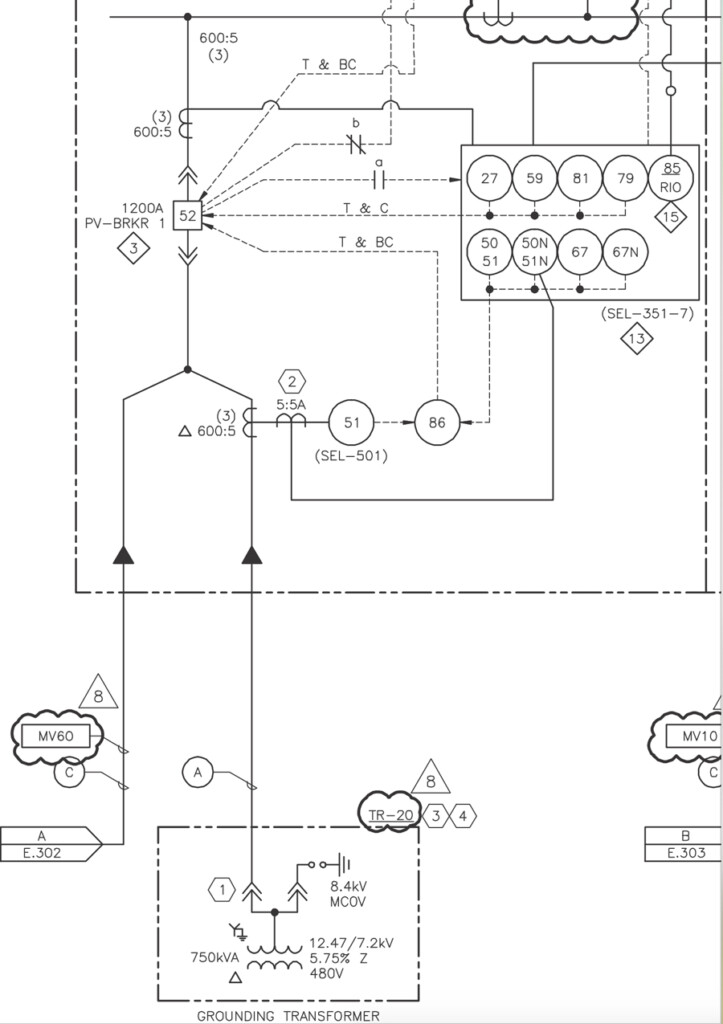
If the grounding transformer is connected to a feeder, special considerations are required to set the protection to properly detect ground current present during ground faults. Figure 1 shows the one-line diagram for a feeder with a grounding transformer that will be used to calculate the protection settings for this guide.
GROUND FAULT CURRENT CALCULATIONS
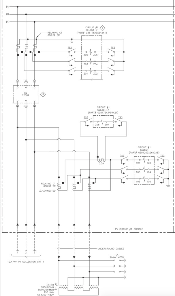
This section shows how to calculate the ground current measured by the feeder relay during ground faults on the 12.47 kV bus. Figure 2 is the corresponding three-line diagram for the one-line diagram shown in Figure 1.
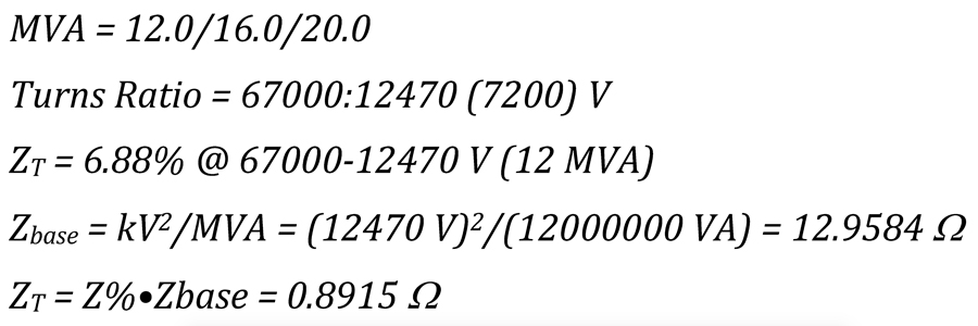
The feeder is served by a step-up transformer with this nameplate data:
The step-up transformer MVA (12) will be used as the system base for the following ground fault current calculations.
Step-Up Transformer Impedance
Grounding Transformer Impedance
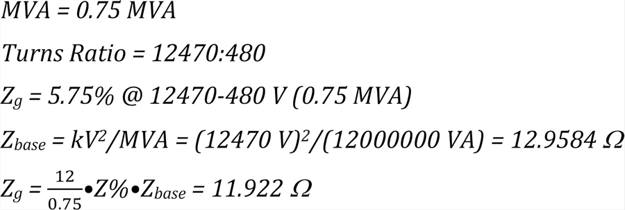
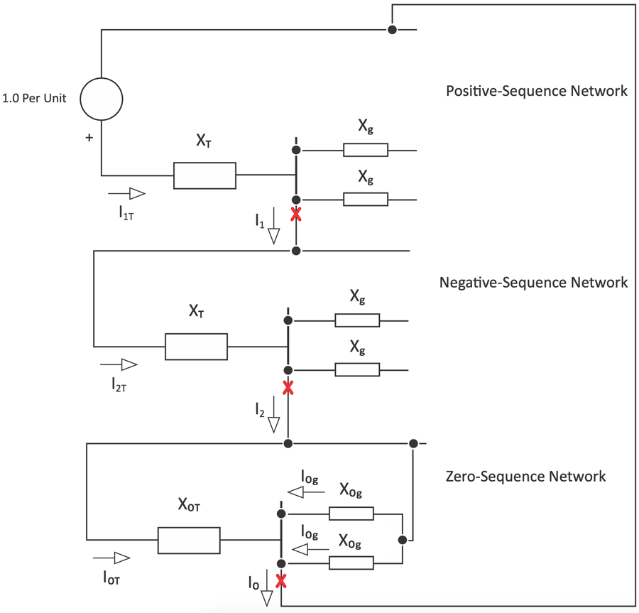
Figure 4 illustrates the short circuit diagram using symmetrical components to calculate the ground fault current available for a single line-to-ground fault on the 12.47 kV bus. The red X denotes the location of the ground fault.
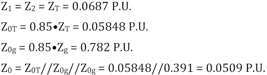
Per Unit Impedances

Network Per Unit Impedances
Ground Fault Current Calculation

Ground Current Flowing Up the Step-Up Transformer Low Side Neutral:

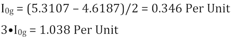
Ground Current Flowing Up the Grounding Transformer Neutral (Per Unit):
Base Current

Ground Current Flowing Up the Grounding Transformer Neutral (Primary)

Neutral Current (IN) Measured by the Feeder Relay

The relay operates on the measured signal IN to detect the presence of a ground fault. Note that this value is equal to I0g since the measurement is taken inside the delta connection of the CTs protecting the grounding transformer. The CT ratio is 600:5.
DETERMINING GROUND FAULT OVERCURRENT PICKUP AND TIME DELAY ON PICKUP SETTING
Set the pickup to reliably detect the presence of a ground fault. The short circuit calculations presented were for the case of a ground fault on the 12.47 kV bus, but the ground fault could be located anywhere along a feeder. As the location of the ground fault is moved along the feeder towards the end, the fault current magnitude drops since the loop impedance increases. Wind farms have long feeders, so it is important to properly set the pickup so that the ground fault overcurrent protection can detect a ground fault located at the end of a feeder.
Set the time delay on pickup long enough to avoid nuisance trips during transient conditions.
CONCLUSION
Grounding transformers are commonly used in the renewable industry. If the grounding transformer is connected to a feeder, special considerations are required to set the protection to properly detect ground current present during ground faults. Additionally, the ground fault overcurrent protection must be set to reliably detect a ground fault located anywhere along a feeder. This article showed how to calculate the ground fault current magnitude for a delta/wye grounded grounding transformer; however, zigzag transformers are also commonly used.
ACKNOWLEDGEMENTS
The author wishes to thank Jesus Vargas for his help in developing the ground fault short circuit calculations presented in this article.

Steve Turner is in charge of system protection for the Fossil Generation Department at Arizona Public Service Company in Phoenix. Steve worked as a consultant for two years, and held positions at Beckwith Electric Company, GEC Alstom, SEL, and Duke Energy, where he developed the first patent for double-ended fault location on overhead high-voltage transmission lines and was in charge of maintenance standards in the transmission department for protective relaying. Steve has BSEE and MSEE degrees from Virginia Tech University. Steve is an IEEE Senior Member and a member of the IEEE PSRC, and has presented at numerous conferences.
CORRECTION
In the Spring 2023 edition of NETA World, a reference on page 10 was incorrectly cited. Reference [1] should read:
[1] Penrose, Howard W. “Why Wind Generators Die Young and How to Make Them Work Longer.” Windpower Engineering. Accessed at www.windpowerengineering.com/why-wind-generators-die-young-and-how-to-make-them-work-longer/.NETA has corrected the information in the online version of the article.