

Large power transformers are widely used in the electrical grid, and interconnecting solar farms to the utility is one of their many applications. To control voltage variations throughout the day, an on-load tap changer (OLTC) is used to adjust the number of effective windings to match the utility’s voltage. Proper functionality of the OLTC requires a specific sequence of operations, and this component must be recommissioned if it is replaced.
Improper replacement of an OLTC can cause severe transformer damage, and traditional protection methods, such as differential protection (ANSI 87), might not detect this condition. Therefore, enhanced protection techniques might be necessary. This article analyzes the improper installation of an OLTC and suggests a protection method to detect this condition.
On-Load Tap Changer Theory
The purpose of a tap changer is to add or remove turns to the windings on either side of a power transformer to increase or decrease the voltage on the coupled side. A no-load tap changer (NLTC) requires the system to be de-energized due to a temporary load loss during the tap change. An OLTC allows a tap change to be performed with the system energized using a make-before-break contact concept.
A live tap change is possible using:
- Resistors and/or reactors that allow current transfer between the taps and limit circulating currents when in parallel
- Bypass switches that allow isolation of the reactors
- Selector switches that perform the actual tap change
- A vacuum interrupter that makes and breaks the current.
Because the make-before-break operation happens at the vacuum interrupter, the oil is not affected by the arc produced during the operation; therefore, contamination is prevented.
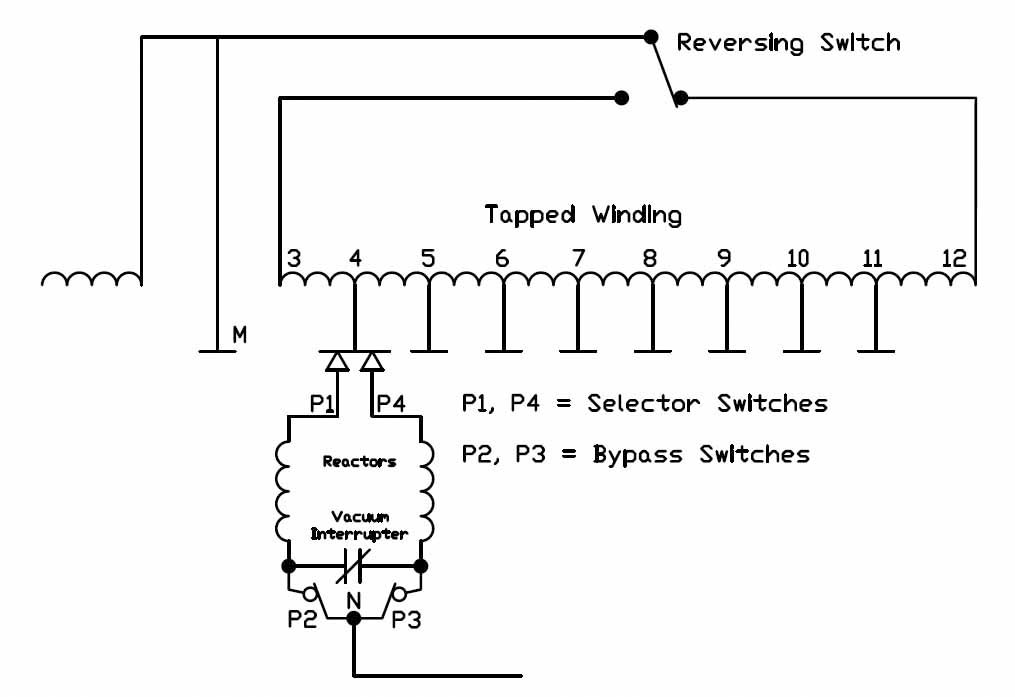
Figure 1: Simplified On-Load Tap-Changer Schematic
The OLTC described in this article is a 32-step, 26.4 kV rated tap changer. A simplified schematic of its winding arrangement is shown in Figure 1. Whenever a tap change is required, the OLTC works in the following manner:
- Switch P3 opens to allow current to flow through the vacuum interrupter.
- The vacuum interrupter opens, and current stops flowing through the right-side reactor (P3–P4).
- As no current is flowing, the selector switch (P4) moves to the adjacent tap.
- The vacuum interrupter closes, and current flows again through the right-side reactor.
- Bypass switch P3 closes, and the tap-changing operation is complete.
A similar operation occurs with the P1 and P2 switches to move the left-side reactor to an adjacent tap.
Existing System
The system discussed consists of a 40 MVA, 138 kV / 34.5 kV transformer, which is wye-grounded connected on both primary and secondary sides, and a delta tertiary. It is connected to utility on the high-voltage side and to a 35 kV bus on the low-voltage side. Contrary to the norm, power flows from the low-voltage side to the high-voltage side via solar inverters connected to two feeders (F1 and F2) at the 35 kV bus. A capacitor bank is also connected to a third feeder at the bus (C). Figure 2 shows a simplified one-line diagram of the system (only the primary relay is shown).
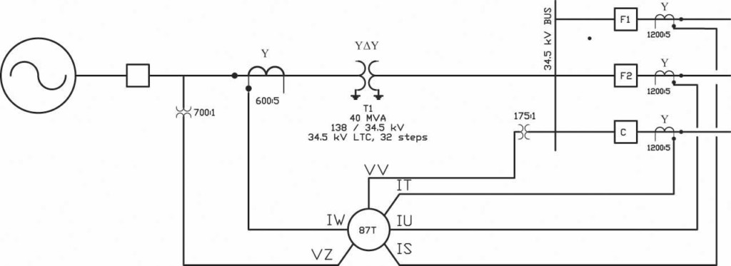
Figure 2: Simplified One-Line Diagram of Existing System
The transformer is protected by primary and backup digital relays. The primary relay’s differential zone of protection includes the transformer, the 35 kV bus, and the breakers connected to this bus. It also senses voltage on both sides of the transformer. The secondary relay’s differential zone of protection includes only the transformer, and the relay only senses voltage on the high-voltage side of the transformer. Because of its more limited capabilities, the backup relay has been omitted from this analysis.
OLTC Installation and Resulting Issues
Due to several leaks and damaged components, site personnel determined that the existing OLTC was defective and needed to be replaced. A new OLTC was installed during a maintenance outage, and the system was re-energized. Shortly after energization, site personnel mentioned that solar inverters began to “trip offline randomly” several times throughout the day. After a few days of continued unexpected outages, an investigation was initiated, and oil samples were obtained from the main transformer and from the OLTC.
The transformer sample did not yield any major issues; however, the OLTC sample yielded an extremely high concentration of several gases, including hydrogen (H₂), nitrogen (N₂), and acetylene (C₂H₂). According to Gill, high concentration of these gases is indicative of high-energy arcing, with the key component being acetylene. Due to the high-energy arcing condition, the transformer was taken out of service immediately and the OLTC installation was investigated. Table 1 shows the gas concentration indicating problems at the OLTC, along with previous values shown for comparison.
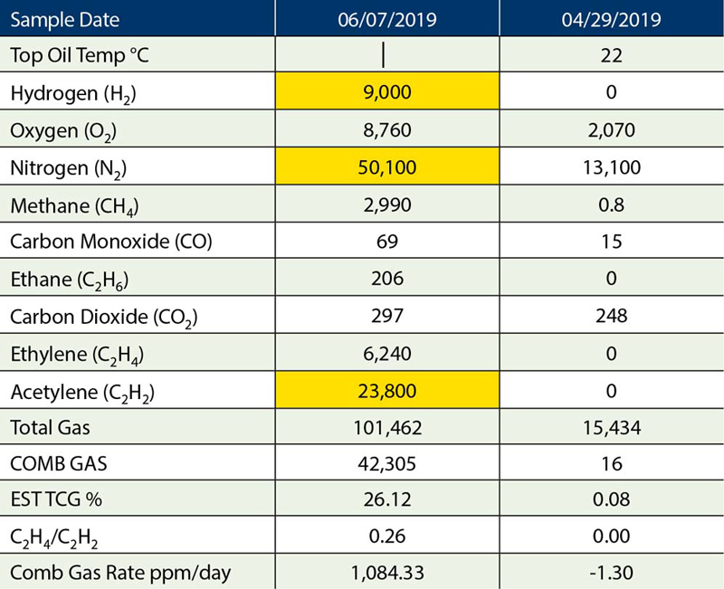
Table 1: OLTC Gas Concentration
As part of the investigation, relay event data was collected and analyzed. A negative-sequence overvoltage event trigger was enabled (V2 > 700 V), and several events were captured. Figure 3a and Figure 3b show the currents observed on 06/06/2019 at 9:11 am on the high-voltage side (channels W and Z) as well as the low-voltage side (channels T, U, and V). At the moment the event was triggered:
- B-phase current collapsed almost to 0.
- The angles of A- and C-phase currents drifted to almost 180 degrees with a slight increase in magnitude.
- B-phase voltage on the 19.9 kV (LN) side increased to 26.1 kV, a 31% increase. There was no change in voltage at the high-voltage side of the transformer.
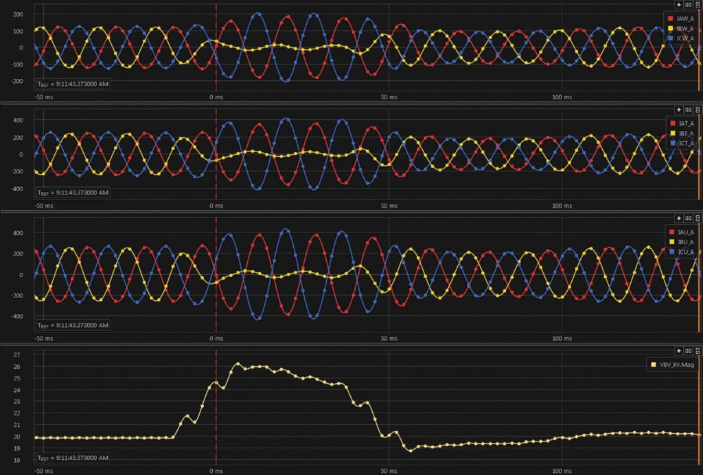
Figure 3a: Phase Currents and B-Phase Voltage
The voltage and current symmetrical components also experienced changes during the event (Figure 4):
- An increase of negative-sequence current (I2) in each set of currents (approximately 80% of nominal)
- An increase in zero- and negative-sequence voltage higher than 5%
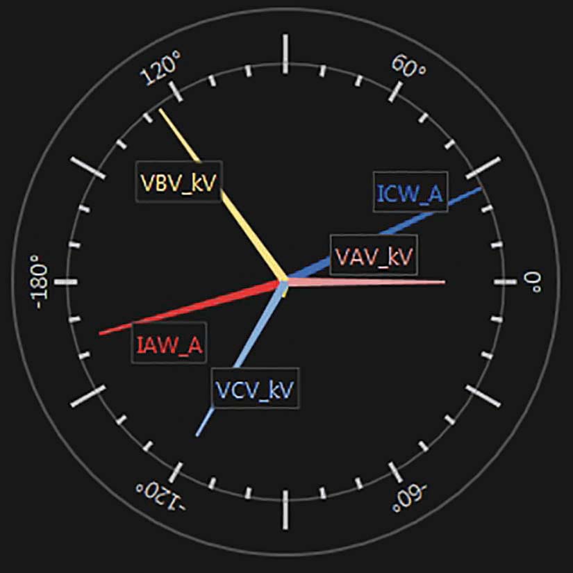
Figure 3b: Phasor Diagram
Because symmetrical components are present during traditional (short-circuit) faults, these should not be used solely to detect OLTC problems. Instead, they can be used as an alarm to indicate a problem is present in the system.
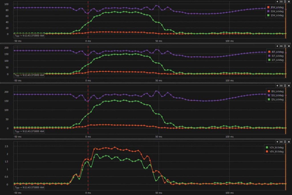
Figure 4: Voltage and Current Symmetrical Components
Harmonic content was also analyzed. The third harmonic (180 Hz) content registered during the event in Figures 3 and 4 exceeded 10% on B-phase voltage. Figure 5 shows the harmonic analysis in the COMTRADE event.
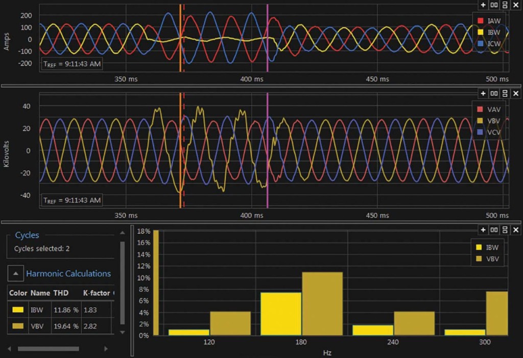
Figure 5: Harmonic Content for VB, COMTRADE Event
Table 2 summarizes the values collected on several events between 6/5/2019 and 6/7/2019:
- B-phase voltage
- Negative-sequence voltage
- Positive- and negative-sequence currents for channels W, T, and U
- 3rd harmonic content
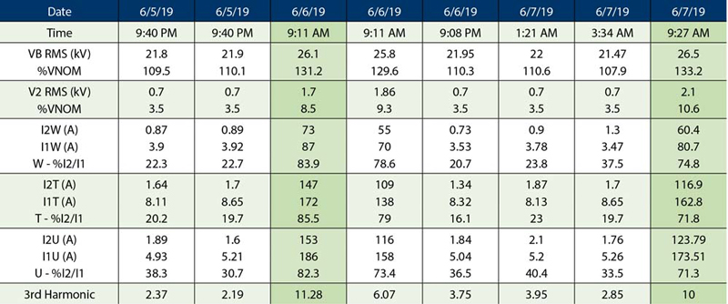
Table 2: Voltages and Currents Observed Using Relay Event Data
The three most extreme cases show:
- Phase overvoltage was higher than 30% nominal.
- Negative-sequence voltage was higher than 5%.
- The I2/I1 ratios are higher than 50% in each set of currents.
- 3rd harmonic content is higher than 5%.
Based on the above observations, a phase overvoltage element on the low-voltage side of the transformer will protect the transformer. An element set at 20% higher than nominal would have tripped the relay in three of the events, while setting it at 10% would have operated in six of the eight events.
The following procedure is recommended:
- Enable an instantaneous phase overvoltage element trip at 20% higher than nominal and a time-delayed overvoltage element trip at 10% higher than nominal (1–2 cycle delay).
- Enable an alarm when the ratio of I2 to I1 is greater than 50%.
- Enable an alarm when V2 is greater than 5%.
- Enable an alarm when the 3rd harmonic content is greater than 5%.
The alarm triggers, as well as the 10% overvoltage delay, are dependent on the relay’s capabilities due to the short duration of these faults and the fast processing interval required.
The new protection elements were tested using the COMTRADE report from the event shown in Figures 3 and 4. Figure 6 shows the oscillography obtained by the newly generated event report, as well as both overvoltage elements (59P1 and 59P2) asserting at 20% and 10%, respectively. The element set at 10% lasted in the asserted condition for 49.95 ms.
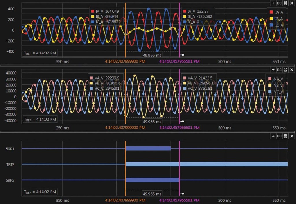
Figure 6: COMTRADE Event Showing Overvoltage Elements
Field Observations
The oil sample results showed a problem in the OLTC, while the relay event data showed the problem was related to B-phase. The OLTC manufacturer provided a procedure to perform raise and lower tests to verify crossed leads. The procedure consists of:
Raise:
- Operate the OLTC in the raise direction from neutral to open P3 and P4.
- Use a continuity tester to verify that P3–P4 is a closed circuit.
- Use a continuity tester to verify that P3–P2, P3–P1, P4–P2, and P4–P1 are open circuits.
Lower:
- Operate the OLTC in the lower direction from neutral to open P1 and P2.
- Use a continuity tester to verify that P1–P2 is a closed circuit.
- Use a continuity tester to verify that P3–P2, P3–P1, P4–P2, and P4–P1 are open circuits.
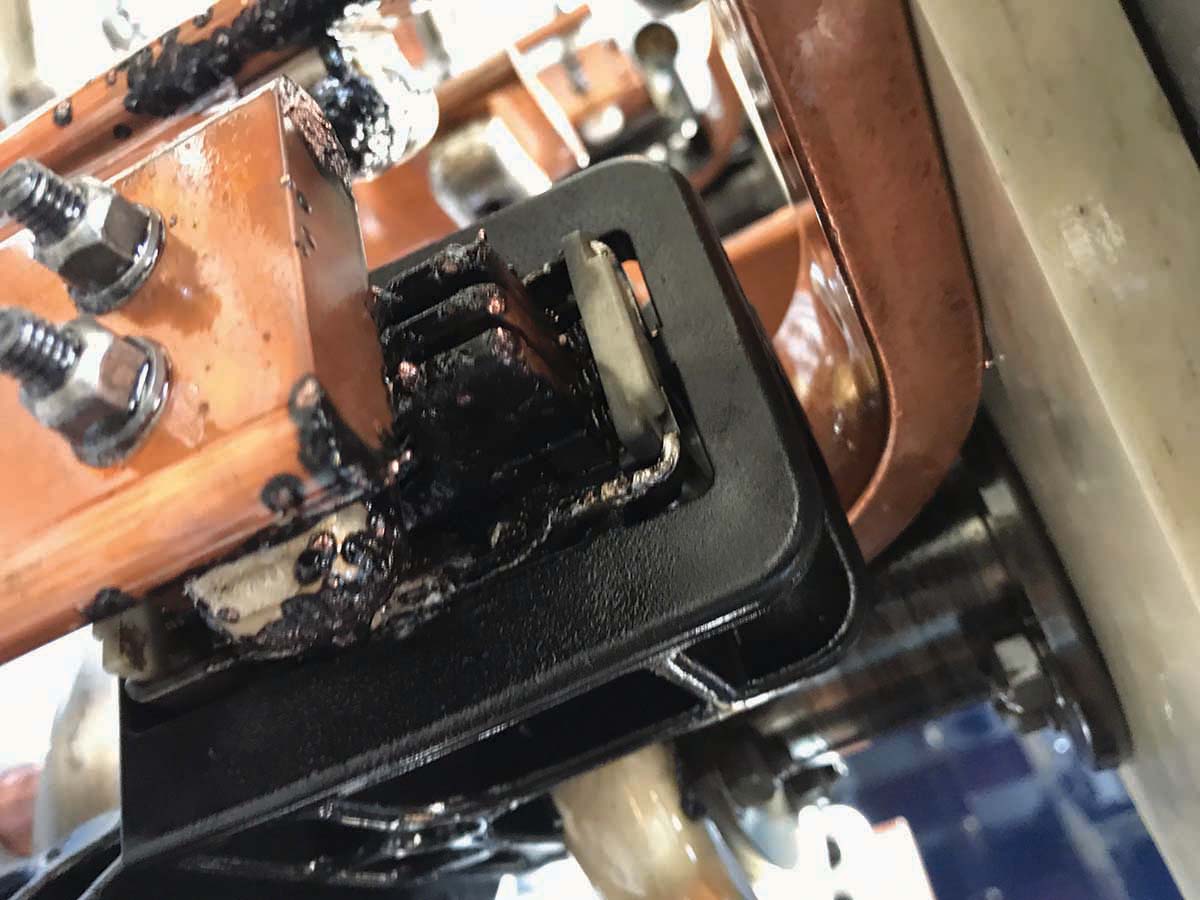
Figure 7a: Damage at the Selector and Bypass Switches Due to Arcing
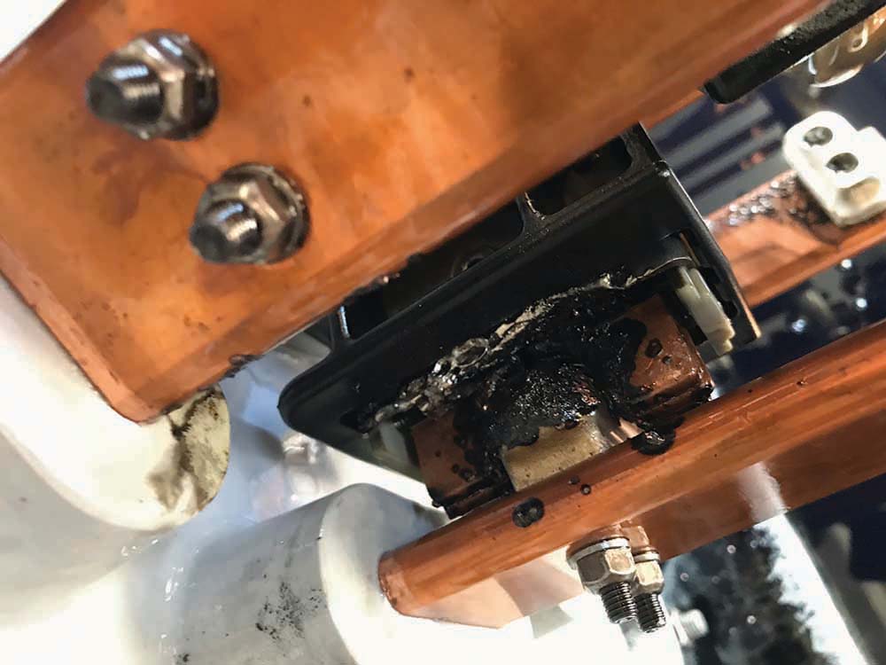
Figure 7b: Damage at the Selector and Bypass Switches Due to Arcing

Figure 7c: Damage at the Selector and Bypass Switches Due to Arcing
These tests were passed on A- and C-phases. However, these tests failed on B-phase — there was no continuity between P3–P4 and P1–P2. A visual inspection showed severe damage at the selector and bypass switches due to arcing during load tap operations (Figure 7a, Figure 7b, and Figure 7c).
Conclusion
An OLTC is an essential transformer component whenever voltage regulation is required while the transformer is energized. The installation of an OLTC requires a test to ensure the leads for the selector and bypass switches have not been crossed. If such leads were accidentally crossed, overvoltage protection elements are needed to send a trip signal to take the transformer out of service before further damage is created. Several alarms using symmetrical components and harmonic content are also recommended to advise site personnel of abnormal conditions.
References
Dohnal, D. On-Load Tap-Changers for Power Transformers, 2009. Available at www.reinhausen.com/PortalData/1/Resources/tc/research_development/vacuum_technology/PB252_en_Power_Transformers.pdf.
Reinhausen Group. On-Load Tap-Changer VacuTAP RMV-II Instruction Manual. Available at www.reinhausen.com/desktopdefault.aspx/tabid-310/94_read-65/.
Gill, Paul. Electrical Power Equipment Maintenance and Testing, Marcel Dekker, 1997. Available at https://neta.netaworld.org/netassa/ecssashop.show_home_category.
Reinhausen Standards. Testing for Crossed Preventative Autotransformer Connections.
 Alex Rangel is a Protection and Controls Engineer for Saber Power Services, LLC. Alex is NETA Level 4 Certified, has been an IEEE member for 11 years, and has been a registered professional engineer (PE) in the state of Texas since 2014. He holds a BS in electrical engineering and an MS in engineering from the University of Texas at Austin.