

The share of wind power in total electric power generation is expected to increase, and with that comes a requirement for this carbon-free source to be more reliable. The wind turbine, which is the most important component of a wind power system, is exposed to harsh environmental conditions and electrical transients such as lightning strikes. Naturally, understanding the lightning protection scheme of the wind turbine and checking its integrity is vital to protect it during lightning strikes such that continued, reliable operation is achieved.
Recent international studies have shown that in one European country, 80% of insurance claims on wind turbines resulted from lightning-related damage. Similarly, a major US utility reported that over 85% of their wind turbine downtime was due to lightning-related damage.
This article provides a general overview of the lightning protection system of a wind turbine, the best practices for lightning protection on wind turbines, and how to verify effectiveness. It discusses the need and advantages of various tests performed to verify the continued integrity of such lightning protection systems, and shares reference quantities for testing parameters and expected results while reviewing some practical and safety considerations.
WIND POWER
Renewable energy — and wind power, in particular — is growing at a rapid pace. In 2020, new installations of wind power provided 93 GW globally. The year-over-year growth is 53% with both the United States and China leading the world in new installations of wind power generation. Wind power answers the pressing needs and circumstances of the day. It is a relatively inexpensive and green energy source that addresses constrained infrastructure budgets as well as climate-change policies. Most market analysts indicate that wind power development will continue to grow at a fast rate because all the driving factors for its adoption persist.
This is great news for the electrical power industry, as there will be growth and opportunity for many years to come. However, this growth will require improved maintenance programs that will protect the investments and maximize the profits from wind power.
LIGHTNING STRIKES
The biggest maintenance problem for wind power is lightning strikes (Figure 1a and Figure 1b). According to Vestas CEO Henrik Andersen, intense lightning strikes were the biggest driving force behind the record warranty claims of €175M (US$212M) in just the second quarter of 2020. Wind turbine manufacturers and installers like Vestas recognize the immense danger of lightning strikes and take great care in the design of turbines. Still, operators and owners of wind turbines must ensure a robust and effective maintenance program for their assets.

Figure 1a: Lightning Damage to Wind Turbines
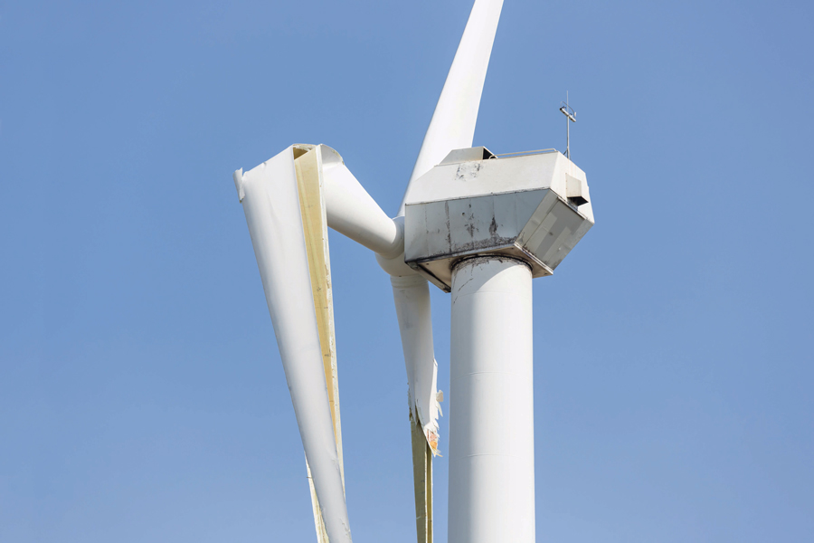
Figure 1b: Lightning Damage to Wind Turbines
LIGHTNING PROTECTION SYSTEMS
A growing number of studies speculate that rotating wind turbines may be more susceptible to lightning strikes than stationary structures. Wind turbines are at an increased risk of being struck by lightning due to their height and the locations used for wind farms. Lightning faults cause more loss in wind turbine availability and production than the average fault. Wind turbines are equipped with lightning protection to minimize damage from direct lightning strikes and to shield sensitive equipment integral to wind turbine operation. A lightning strike would not only have a large magnitude of current but would also impress an unwanted electromagnetic field across components housed in the nacelle and base of the tower. The lightning protection system (LPS) performs the function of directing the current strikes to ground.
Lightning Protection Zones
To facilitate the coordination of protections functions, it is prudent to divide the wind turbine into lightning protection zones (LPZ). The lightning protection zone concept is a structuring measure for creating a defined, electromagnetically compatible environment in an object while being cognizant of the object’s stress withstand capability.
IEC 62305, Standard for Lightning Protection defines the LPZ for structures and can be applied to a wind turbine. The zones are classified into external and internal zones based on their exposure to direct lightning.
External Zones
- LPZ 0A is the zone where the threat is due to the direct lightning flash and the full lightning electromagnetic field. The internal systems may be subjected to full lightning surge current.
- LPZ 0B is the zone protected against direct lightning flashes but where the threat is the full lightning electromagnetic field. The internal systems may be subjected to partial lightning surge currents.
The rolling sphere method is used to determine LPZ 0A — the parts of a wind turbine that could be subjected to direct lightning strikes, and LPZ 0B — the parts of a wind turbine that are protected from direct lightning strikes by external air-termination systems or air-termination systems integrated in parts of a wind turbine (for example in the rotor blade), as seen in Figure 2 and Figure 3.
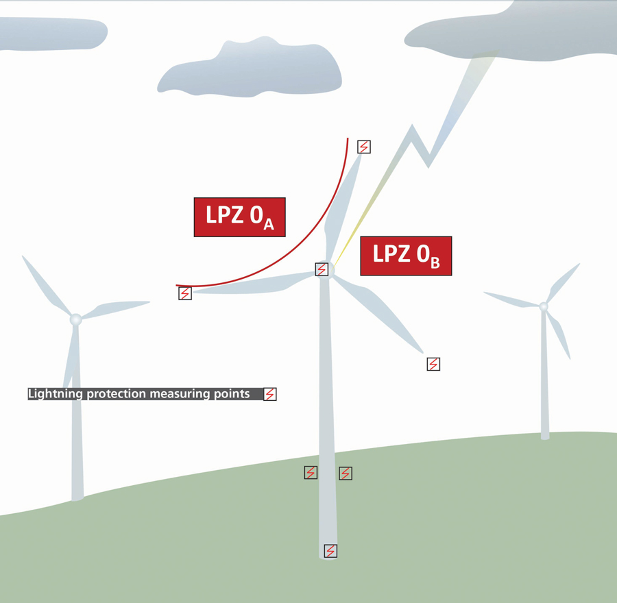
Figure 2: Simplified Wind Turbine External LPZ
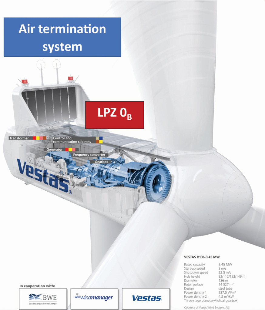
Figure 3: Air Termination Systems Installed for Wind Turbine Nacelle
Internal Zones
- LPZ 1 is the zone where the surge current is limited by current sharing and isolating interfaces and/or by surge protection devices (SPD) at the boundary. Spatial shielding may attenuate the lightning electromagnetic field.
- LPZ 2 to LPZ n are the zones where the surge current may be further limited by current sharing and isolating interfaces and/or by additional SPDs at the boundary. Additional spatial shielding may be used to further attenuate the lightning electromagnetic field.
The LPS essentially works by taking the form of a low-resistance path to ground. The path goes from the blade’s tip to the base of the turbine. This path is shown in Figure 4 and Figure 5.
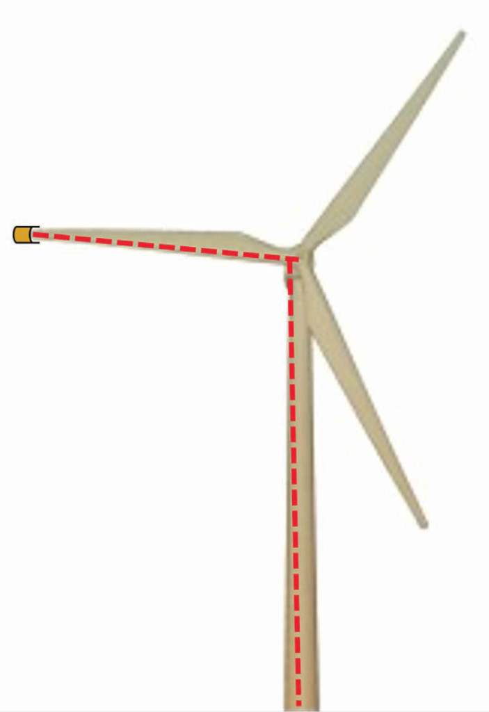
Figure 4: Current Path for Lightning Discharges
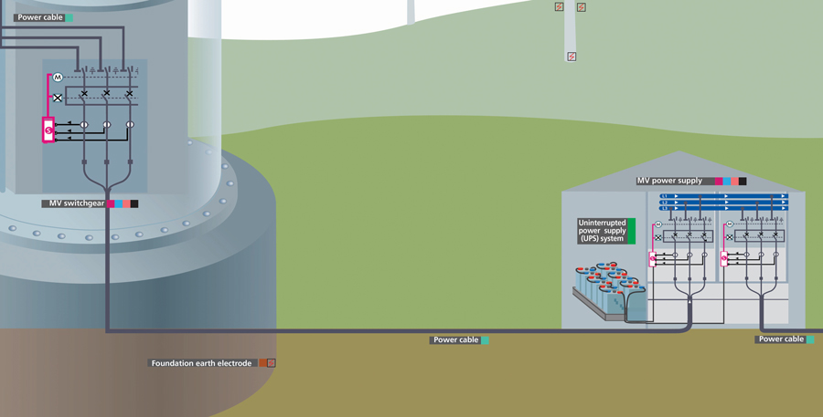
Figure 5: Foundation Earth Electrode at Wind Turbine Base
In the event of a lightning strike, current will flow to ground through the lightning protection system, not the sensitive equipment in the wind turbine. As the lightning current is dissipated through the grounding system, it is important to not cause thermal or mechanical damage or arcing that may lead to fires or personnel injuries. To ensure that protection in the above zones will work when needed, the resistance of the path to ground should be measured at regular intervals, making sure it meets the limits specified by the turbine manufacturer (typically limited to 15–30 mΩ, depending on turbine size). For these tests, use of a low-resistance ohmmeter is recommended.
METHODS TO VERIFY LIGHTNING PROTECTION SYSTEMS
Measurement of low resistance is affected by key factors such as measurement type, test current magnitude, length of measurement leads, and placement of leads/probes.
Four-Wire Method
The four-wire method (Figure 6) is most appropriate because it uses separate current probes to inject direct current (DC) and separate potential probes to measure the voltage drop across the test specimen.
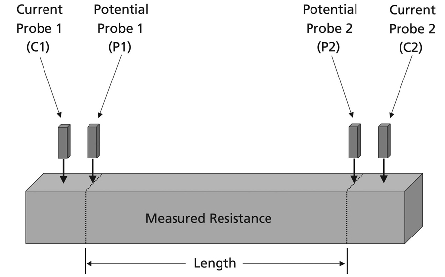
Figure 6: Four-Wire Method
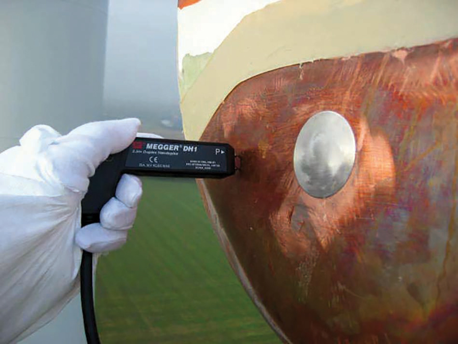
Figure 7: Lightning Conductor Resistance Measurement at Blade Tip
In some practical cases, a Kelvin measurement — where current and potential probes are 180° apart — is also employed to measure low-resistance values. The use of any other methods such as a two-wire method may not be suitable, as the measurement contains contact resistance values of the probes, thereby clouding the measurement.
Testing Wind Turbine Lightning Protection
As introduced in the preceding sections, the most important part of the LPS is to test the conductor from the blade tip to the down conductor inside the hub that ultimately connects to the ground grid as was shown in Figure 5 and is depicted in Figure 7 and Figure 8.
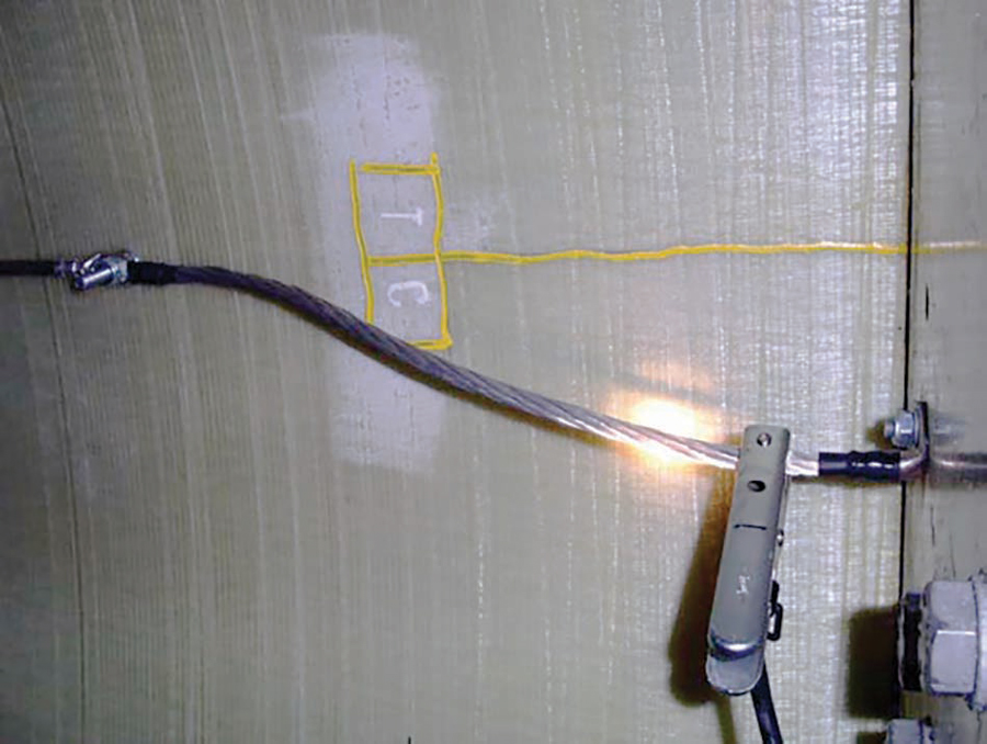
Figure 8: Lightning Conductor Resistance Measurement at Wind Turbine Hub
This conductor is placed under significant strain as the blade flexes with the wind during normal operation. Under strain, the conductor may fracture. Unfortunately, it is not enough to simply check continuity because, if the fractured conductor is touching at the break point during a continuity test, the result will not be satisfactory. Consequently, a test current magnitude of 1 A or more is recommended for this test.
The length of a turbine blade can be seen in Figure 9. The size of the turbines poses a problem because low-resistance ohmmeter test leads are typically very short. Due to the size of the wind turbines, some extra-long leads are required, often up to 100 m. This is a huge increase in length over standard test leads for low-resistance ohmmeters. The long leads must be designed with a low enough resistance to ensure that a measurement is still possible. To achieve this, it is important to understand the test instrument design.
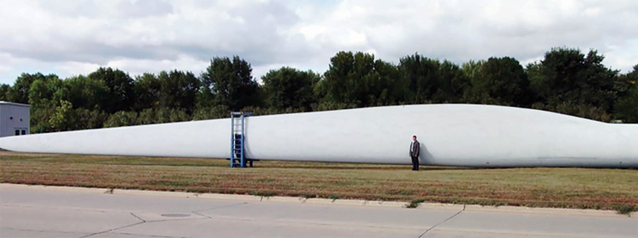
Figure 9: Wind Turbine Blade before Installation
Some instruments have a compensation factor to allow for power loss in standard test leads. When using long test leads, the compensation for power loss will no longer be sufficient. As a result, the test range of the instrument will be reduced. When the resistance of the test leads is increased, the total value of R in the following equation will also increase.
P = I2R
where
R = (resistance of load) + (resistance of
test leads)
P = output power of the test instrument
I = output current of the test instrument
Since the maximum power output (P) of the test equipment cannot change, the rise in test lead resistance will cause the maximum current (I) to be reduced. Table 1 shows how lead length impacts the ability of an instrument to measure low resistances. It is clear that accurate and repeatable measurements will be a combination of test current, lead length, and resolution.
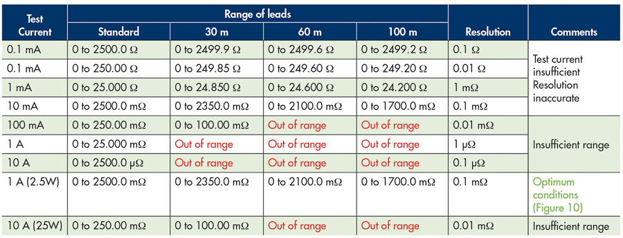
Table 1: Resistance Range for Varying Test Current Magnitudes for a Popular Low-Resistance Tester
As seen in Figure 10, the performance of the low-resistance tester at 1 A (2.5 W) was most desirable for lead lengths that are typically employed to measure wind turbine LPS. For wind turbine applications, it is important to utilize the proper range and test current magnitude because it will be imperative for the length of measurement leads to accommodate the length of the wind turbines blades.
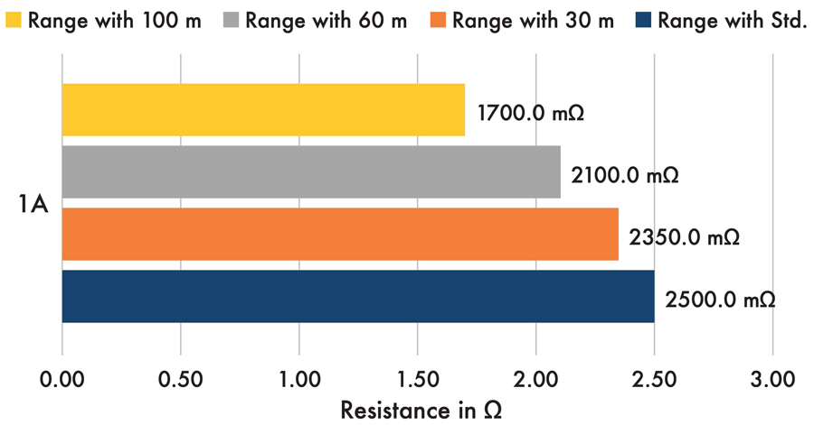
Figure 10: Optimum Testing Parameters with 1 A Test Current and Long Leads
RESULTS
Testing the lightning protection system was performed on a wind turbine with 32-m-long (105-ft) blades using a low-resistance ohmmeter. The instrument was used in its long-test-lead mode, which applies a 1 A test current and can measure accurately down to 0.01 mΩ when using 100-m-long (330-ft) test leads. The lightning system testing consisted of measuring the system’s resistance from the tip of each blade to the hub and from the hub to the base. The lightning system terminates with interconnected ground rods at the base of the turbine tower.
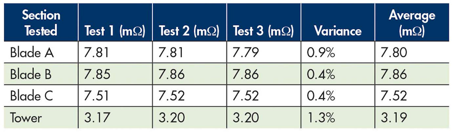
Table 2: Raw Measurements, Variance, and Averages
Each measurement was taken three times to evaluate repeatability. The variance meter on the instrument automatically recorded three measurements in a row and calculated their variance. The raw measurements of this test can be seen in Table 2; total results are shown in Table 3.
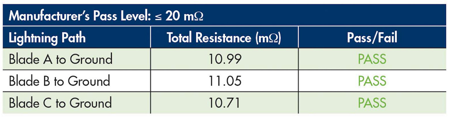
Table 3: Total Resistance Values and Results
The low variance provides confidence in the measurement. In the field, test engineers must take every care to remain safe and follow best practices. This will provide the best possible measurements.
The manufacturer of this wind turbine provided a pass level for the lightning system of 20 mΩ or less. This test proves that the lightning system has been installed correctly and is in good working order. Therefore, this turbine has good lightning protection as per the manufacturer’s design.
CONCLUSION
Lightning is a hugely damaging threat to wind turbines, and as wind power installations continue spreading across the world, the requirement to protect these assets becomes more important.
Manufacturers of wind turbines take great care in designing the lightning protection system because of the known damage that can be caused. Owners and operators of turbines must ensure that the lightning protection system has been installed correctly. Additionally, owners and operators must regularly check the lightning protection system as part of the maintenance program.
Testing and verifying the lightning protection system is based primarily on low-resistance measurements. There are some challenges to measuring resistances at milliohm level when dealing with large structures like a wind turbine, so a balance between test energy, accuracy, resolution, and test lead length must be established. However, the right tools for the task will make it a simple job.
It is highly recommended to make lightning protection maintenance a key regular task for owners and operators. This will avoid lightning damage to wind turbines and ensure these assets are protected.
REFERENCES
Dehn International. “Lightning and Surge Protection for Wind Turbines,” 2015. [Online]. Available: https://www.dehn-usa.com/sites/default/files/uploads/dehn/pdf/white-papers/ab-juli15/wp016-e-wind_turbines.pdf.
Megger Instruments Ltd. Wind Farm Testing – Growth Applications, 2021.
Vestas Wind Systems A/S. Installation of Copper Tip – Work Instruction, Vestas.
A. Z. Kattamis and M. Pooley. “Lightning Protection for Wind Turbines,” Electrical Engineering & Computer Science, 2017.
Megger Limited. “Testing Wind Turbine Lightning Protection,” Application Note, June 2019.
Furse. Guide to BS EN/IEC 62305.
American Clean Power. “Wind Power Facts,” [Online]. Available: https://cleanpower.org/facts/wind-power/.
Global Wind Energy Council. “Global Wind Report,” Global Wind Energy Council, Brussels, 2021.
 Sameer Kulkarni, PE, is an Applications Engineer at Megger. He previously worked for Entergy at River Bend Nuclear Generating Station as Systems Engineer responsible for power distribution, large power transformers, and NERC. Sameer obtained his BS in Mumbai, India, and graduated with an MS in electrical engineering from Arizona State University. He obtained his Professional Engineer license in June 2019 and is an IEEE Member.
 Dr. Ahmed El-Rasheed is a Business Development Director at Megger and has over 14 years’ experience in electrical engineering. He is a member of several international standards organizations and has published papers on ground testing, insulation testing, and multi-sensor integration using AI.