
High voltage is defined by the National Electrical Code (NEC) as any voltage over 600V and by the International Electrotechnical Commission (IEC) as any voltage greater than or equal to 1,000V. NETA uses the IEEE definition: any voltage greater than or equal to 100kV and less than or equal to 230kV. Other standards and industries define high voltage at different levels. This can lead to confusion with regard to nomenclature, but in this case, it is relative to the application. For every normal operating voltage level used by electrical equipment, there is a corresponding test voltage and a method of applying that voltage for a particular type of equipment according to the tests and standards being applied.
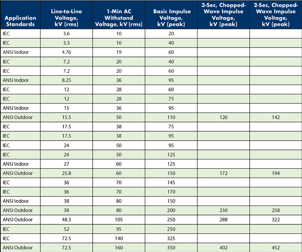
Table 1: ANSI and IEC Voltage Rating Chart
From low- to ultra-high voltages, all electrical equipment requires some type of electrical insulation to separate circuits from each other and/or from grounded connections. Insulation materials include solid insulation and/or air, vacuum, liquid, or gas mediums. Most standards outline basic conductor clearances and phase spacing, but many details that affect the high-voltage characteristics of equipment are the responsibility of the manufacturer.
Vacuum interrupter manufacturers perform special operations to smooth the contacts and other internal conducting surfaces on the finished units to enhance their dielectric performance, which is gauged through high-voltage testing. More often, high-voltage equipment manufacturers combine technologies to increase the overall performance of the equipment; this includes the use of dry insulating gases with vacuum interrupters for use in applications well over 100kV. Design and production tests may include basic insulation level, chopped wave insulation level, dielectric withstand, critical flashover voltage, as well as many other application-specific tests.
Over time, insulation systems begin to deteriorate due a number of operational and environmental factors, including contamination, mechanical effects, thermal aging, partial discharge, and over-voltage spikes; these eventually lead to failure of the system. Degradation of insulation can lead to equipment failure and loss of assets as well as injury or death to personnel. Numerous types of high-voltage tests require a laboratory environment due to environmental factors, test levels, and equipment requirements. For example, partial discharge tests require an environment with low electrical noise for sensitive measurements of voltage fluctuations. Contamination tests for some products require the test sample to be mounted on a rotating wheel that intermittently submerges the product in a temperature-controlled bath of a preselected contaminant — often while under test — to simulate worst-case environments and accelerate aging. Some test labs are capable of performing high-voltage tests while simulating atmospheric pollution, rain, fog, snow, or ice via spray nozzles or misters.
Evolution of HV Lab
The need for high-voltage testing was established with the advent of high-voltage power generation and transmission in the late 1800s. The individual components that made up high-voltage systems needed to be tested to ensure they could reliably operate at the required voltage level and withstand surges in voltage generated from events such as lightning strikes or short circuits.
In the early days of electricity, there were no industry design or testing standards, so equipment manufacturers were responsible for selecting their own test procedures and levels. Manufacturers often had inadequate laboratory facilities, so tests were performed in cooperation with a local utility at a high-voltage substation. Varying test procedures and levels inevitably led to compatibility issues between different types of equipment and those manufactured by different companies such as the burning of wooden insulator pins on high-voltage transmission lines.
The first attempt at standardization in the United States came with the creation of the American Institute of Electrical Engineers (AIEE) in 1884. However, the first standard was not adopted until 1893, and that standard was related to the use of units and symbols. It wasn’t until 1903 that the first technical committee — the High-Voltage Transmission Committee — was formed. By this time, transmission systems as high as 60kV were operated in some parts of the world, and the industry was growing rapidly. At present, numerous electrical standards are used across the world, including IEEE, ANSI, ASTM, UL, CSA, IEC, ICEA, and AEIC, as well as utility-specific standards, and high-voltage transmission lines are now operated at voltages in excess of 1MV.
Manufacturers of electrical equipment often certify their products in accordance with multiple test standards to ensure their equipment fits the requirements of the region where it is being sold. High-voltage labs provide independent, third-party performance of these tests to provide customers with reliable, unbiased results. The theory of high-voltage testing has not changed tremendously since the early days of electricity. However, there have been substantial improvements in the technology required to perform testing and to measure the results accurately and precisely.
From measuring high voltages based on the breakdown distance of an air gap, to Fleming’s oscillation valve, to vacuum tubes, to the analog-to-digital converters used today, the accuracy and precision of high-voltage measurement has improved by magnitudes. Access to the high-voltage equipment necessary to perform the same tests offered at world-renowned testing labs has also become more widespread. Once, just a handful of high-voltage test labs were available; due to the proliferation of higher-voltage products and the availability of test equipment, hundreds of labs are now capable of performing many of the design and production tests manufacturers require.
A modern high-voltage laboratory can evaluate the design, configuration, and materials of many types of high-voltage equipment — including circuit breakers, transformers, insulators, cables, and motors — for suitability, reliability, performance, and safety. New products can be tested to ensure they conform to design specifications as well as national and international standards, existing equipment conditions can be reevaluated after modifications, and failed equipment can be analyzed to find a root cause.
High-Voltage Lab Utility
Examples of high-voltage testing include:
- Basic insulation level (BIL) test of a new primary disconnect design. Even though switchgear may have been tested and certified previously, any change to the system, such as a primary disconnect design using new methods or materials, warrants additional testing and possible recertification of the switchgear. Any change to the system, including changes in design, insulation distance, materials, insulating medium, etc., could affect overall performance. BIL testing generally takes place inside a high-voltage lab due to the size of the test system — which consists of a capacitor bank, charging circuit, voltage divider, and high-speed analog-to-digital measurement equipment — and environmental factors such as temperature and humidity.
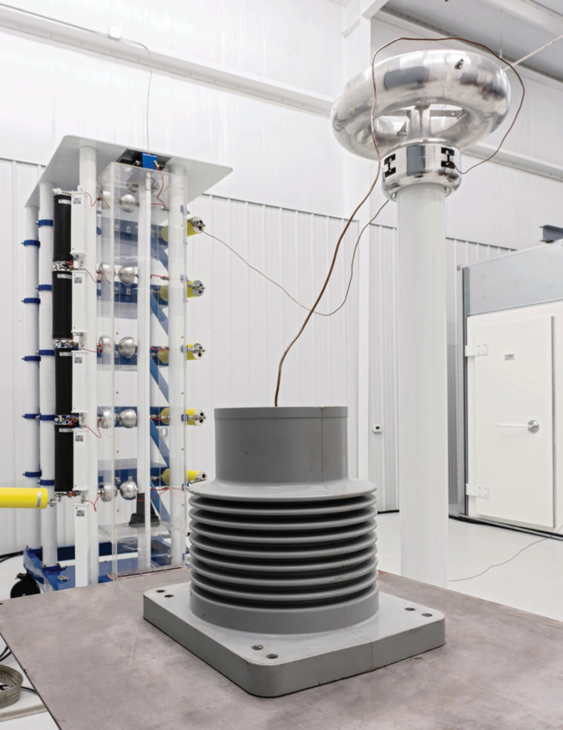
BIL Test
- Partial discharge test of a molded insulator design. The process of manufacturing a molded insulator can leave small voids inside the finished insulator. These voids act as capacitors inside the solid insulation and produce reoccurring discharges that do not fully bridge the space between the two conductors — hence, partial discharge. This will lead to erosion of the solid insulation and eventual insulation breakdown. To obtain an accurate measurement of partial discharges, sensitive voltage measurement equipment must be used, usually in the form of a coupling capacitor and partial discharge detection circuit. Measurements must often be taken inside an environment with low electrical noise such as a Faraday cage.
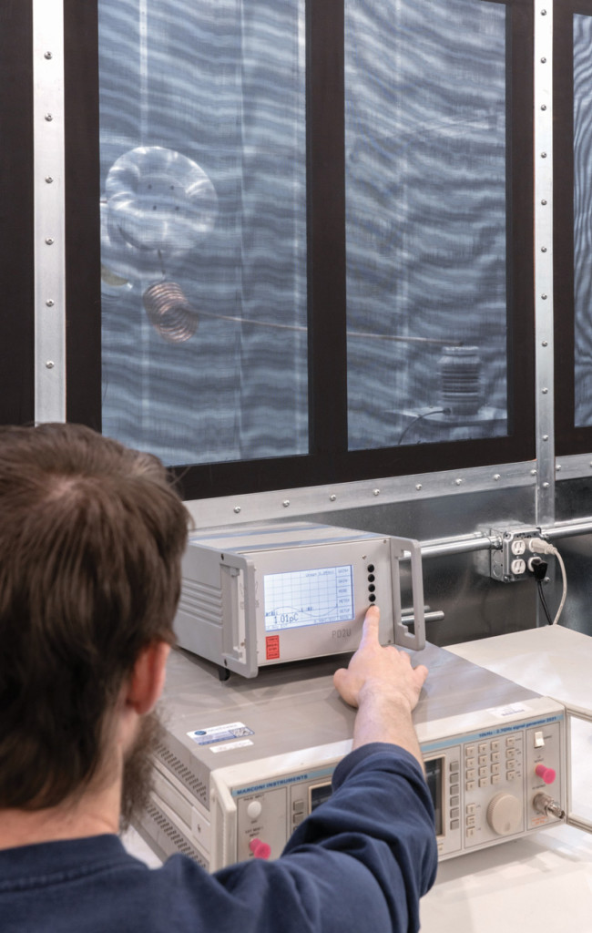
Partial Discharge Test
- Dielectric breakdown test on a new insulator design. The dielectric breakdown test is a common design test performed on insulators before entering production to determine the voltage at which an insulator can no longer withstand the voltage being applied, which leads to internal or external flashover. This helps manufacturers refine their designs to enhance performance and reliability.
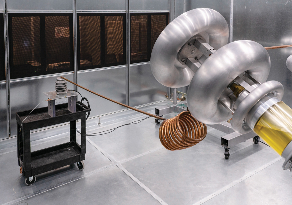
Dielectric Breakdown Test
HV Lab Benefits
High-voltage test labs provide an indispensable source of information that ultimately improves the overall reliability, performance, and safety of electrical products and systems. Independent, third-party testing of electrical products helps prevent bias and improves the accuracy of a product’s electrical specifications. Accrediting bodies such as ISO help identify high-quality testing laboratories. Information gathered at a high-voltage lab can help companies further advance electrical technologies, improve the reliability of existing electrical systems, and keep users and operators safe from harm.
Standard High-Voltage Lab Tests
- Partial Discharge
- Radio Interference Voltage – RIV
- Visual Corona
- Temperature Rise
- Chopped Wave Impulse
- Dielectric Breakdown / Dielectric Withstand
- AC Short-Term and Long-Term Withstand
- Dry Lightning Impulse Critical Flashover and Withstand
- Vibration
- Accelerated Life
- Environmental
- Mechanical Endurance
- Speed, Velocity, and Motion
- Seismic
References
National Fire Protection Association. NFPA 70, National Electrical Code, 2008 Edition.
International Electrotechnical Commission. IEC 62271-1, High-voltage switchgear and controlgear – Part 1: Common specifications, 2007 Edition.
ANSI/NETA ATS, Standard for Acceptance Testing Specifications for Electrical Power Equipment and Systems, 2017 Edition.
American Institute of Electrical Engineers (AIEE). “High-Tension Power Transmission,” McGraw Publishing Company, New York, 1905.
Koepfinger, J. “History of Institute of Electrical and Electronic Engineers (IEEE) Standards.” Engineering and Technology History Wiki (ETHW), Available online: www.ethw.org/History_of_Institute_of_Electrical_and_Electronic_Engineers_(IEEE) Standards, accessed November 21, 2018.
 Jerod Day is Vice President of Vacuum Interrupters, Inc., which specializes in vacuum interrupter design and testing. He has five years of field experience with medium-voltage circuit breakers and switchgear. Jerod has coauthored articles in publications including the Journal of Heat Transfer. He received his MS degrees in mechanical and energy engineering from the University of North Texas, Denton, Texas.
 Finley Ledbetter is the Chief Scientist for Group CBS, Inc. He has more than 40 years of power systems engineering experience. Finley is a member of the IEEE, past president of PEARL, and a frequent contributor to NETA World Journal. He received NETA’s Alliance Recognition Award in 2016.