

There are no one-size-fits-all solutions to the ground fault-protected main circuit breaker issue. Diligent attention to the requirements in the NEC — NFPA 70 and the equipment in the existing installation is required.
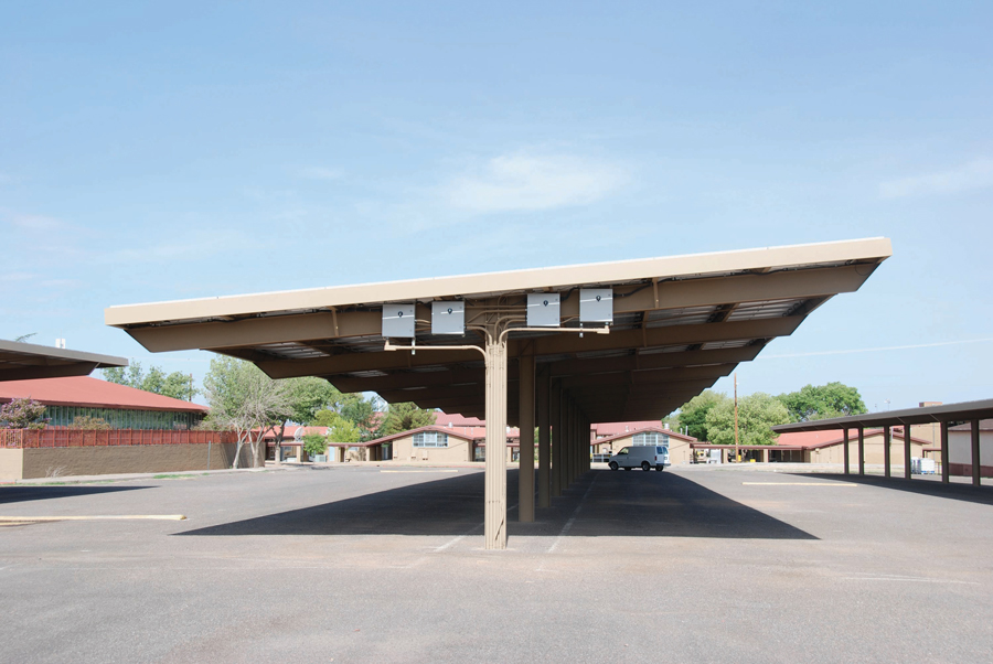
Typical School Carport
The 2020 National Electrical Code (NEC – NFPA 70) in Section 230.95 Ground-Fault Protection of Equipment requires ground-fault protection of equipment for solidly grounded wye services of more than 150 volts but not exceeding 1,000 volts phase to phase. While this type of service is not common in residential/dwelling services, it is quite common in medium-size commercial electrical installations such as schools, big-box stores, and supermarkets. Load-side PV system connections (705.12) are attractive in these situations because the large panelboards/load centers offer a relatively easy method of making the connection (Photo 1).
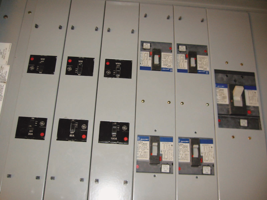
Photo 1: Large Panelboard in a Commercial Building Providing Several Potential Load-Side Connection Points
However, Section 705.32 must be addressed, and other factors should be investigated before the decision is made to make a load-side PV connection.
THE BASICS
A major consideration revolves around the common use of a main circuit breaker that is equipped with a GFP accessory. Circuit breakers are manufactured with numerous optional accessories, including (depending on manufacturer and model) shunt trips, auxiliary switches, remote indicators, power operation, adjustable trips, and ground-fault protection (GFP) trip mechanisms (Photo 2).
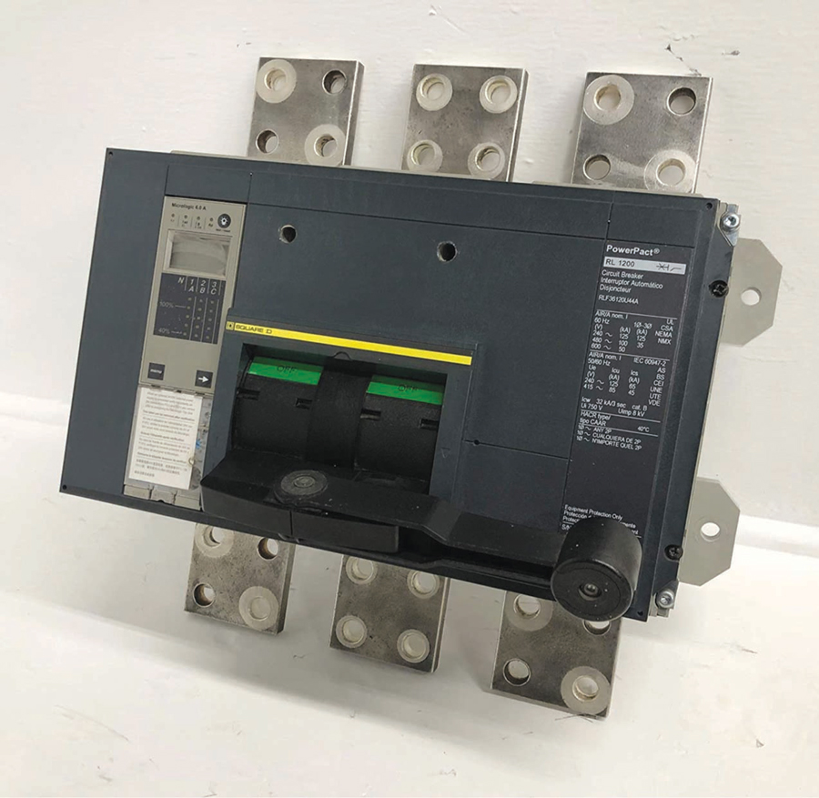
Photo 2: 1,200-Amp Circuit Breaker with Ground Fault Protection
While UL Standard 489 requires tests to evaluate the backfeeding of the basic circuit breaker, most of the accessories are not evaluated for backfeeding. In fact, backfeeding may have no effect on many of these accessories, and specific testing for backfeeding may be unnecessary.
However, older and possibly some current ground-fault trip mechanisms may be damaged if the circuit breaker has voltages on both line and load terminals after the circuit breaker has been opened by a ground-fault trip. UL Safety Standard 489 for molded-case circuit breaker testing does not evaluate the GFP accessory on backfed GFP main circuit breakers in a manner that subjects the ground-fault device to the conditions it would experience in a utility-interactive PV system or possibly even in a parallel-connected generator installation where line and load terminals are both energized during and after a ground-fault trip. PV inverters responding to internal anti-islanding software may have energized outputs up to two seconds after the AC utility power is removed from the inverter output. These PV inverter-energized load-side terminals on the main circuit breaker may cause the GFP trip mechanism to be destroyed if that trip mechanism is connected to and receives power from the main circuit breaker load-side output terminals. In normal operation with no PV, when a ground-fault event occurs, the opening circuit breaker immediately removes the power source for that GFP trip mechanism, and no damage will occur.
Circuit breaker manufacturers should be evaluating all accessories supplied with their circuit breakers for operation under all possible application configurations. However, utility-interactive inverter installations are a relatively new application, and PV inverters are being applied to electrical installations that may be decades old.
Discussions with technical support personnel at circuit breaker manufacturers indicate that most new designs use a current transformer to power the GFP device and that the current transformer does not respond to any potential voltages on the load terminals of a tripped-open main circuit breaker. The GFP device, powered by the current transformer, should not be damaged by backfeeding or by inverter supplied voltages on the output terminals of a tripped open main circuit breaker.
However, there is some confusion and uncertainty about older GFP/circuit breaker designs that have been installed widely and may still be found in older buildings.
LOOKING DEEPER
Load-Side Connections Where a GFP-Protected Main Circuit Breaker Is Involved
Section 705.32 requires a supply-side connection of a PV system where a Section 230.95 ground-fault protected main service disconnect is involved, but the exception allows load-side PV connections with requirements for ground-fault protection of the loads from all ground-fault sources.
If the circuit breaker manufacturer (design engineer) will sign a statement that the specific main circuit breaker with GFP accessory by part number and model number will not be damaged under PV inverter backfed conditions (line and load terminals energized at the same time during and after the GFP device trips the circuit breaker), then it appears that backfeeding that circuit breaker may be acceptable and a load-side PV connection may be possible. Bulletins and information from sales departments are sometimes insufficient to make a safe determination.
After determining that the main circuit breaker/GFP is suitable, the issue of protecting the load circuits or feeders during ground-fault conditions from all sources, utility, and PV must be addressed (705.32 EX). An engineering analysis would be required that shows how and where ground-fault currents are sourced. What impedances are involved in the utility source and the PV source, and how much current can each supply under varying types of ground faults? Ground faults are not always hard, low-resistance faults and may be arcing faults of varying impedances. Suppose the PV system provides enough ground-fault current to prevent the main circuit breaker GFP from tripping. How is the ground fault contained or interrupted?
Some manufacturers and installers are wary of connecting some sort of GFP device to the inverter output because this is a non-standard connection, and any ground faults detected might only be those originating between the device (usually a backfed circuit breaker) and the inverter, not ground faults occurring in load circuits. This would occur if a GFPE circuit breaker were to be used in an AC inverter combining panel since that circuit breaker would normally sense ground-fault currents only toward the inverter from the circuit breaker location.
Several manufacturers offer a main circuit breaker GFP that can take inputs from multiple ground-fault sources like a dual-utility feeder system. But these would be found in limited, special instances where there are multiple utility sources, and they may not be useable to meet NEC requirements in the PV applications.
Other Considerations
The NEC requirements in 705.32 and 705.12(B) might appear to restrict the PV to always be 20% or less of the main circuit breaker rating, and the main GFP circuit breaker will always trip on a ground fault, but what was the GFP trip setting? On a 1,200-amp GFP circuit breaker, the GFP adjustable trip setting might be from about 200 amps to 1,200 amps of fault current. For a load with multiple ground-fault current sources (at least one from the utility and one or more from current-limited utility-interactive PV inverters), what would the proper trip settings be for each ground-fault device?
Under the 2017 NEC and 2020 NEC, the 120% allowance in 705.12(B)(2) may apply to the installation. But it may not. A relatively large PV system with a small main circuit breaker on a large busbar could meet either the 120% or the 100% allowance.
The 2020 NEC still has the basic requirement for ground fault protection in 705.32. If a supply-side PV connection is elected, the new Section 705.11(E) will apply. This section has been interpreted as requiring ground-fault protection for PV circuits and PV equipment when they are connected to services rated at 1,000 amps or more. This requirement would mean that a properly rated backfed circuit breaker with a ground-fault accessory be used as the PV system disconnect at the point of connection to the service conductors.
Historical Perspective
About 15 years ago, two PV-progressive electric utilities headquartered in Phoenix, Arizona, (Arizona Public Service and Salt River Project) decided to put medium-size PV systems (18–60 kW) on numerous schools in their respective service territories (see opening photo and Photo 3).

Photo 3: PV System Mounted on School Carport
These schools typically had services that met the NEC 230.95 requirements and were equipped with ground-fault protected main circuit breakers. Some were brand-new schools, while many were quite old. Getting data on old, discontinued main circuit breakers with GFP accessories was difficult, if not impossible. As previously mentioned, the large 1,000-amp-plus panelboard/load centers in these schools presented an attractive location to make a load-side PV connection. However, exhaustive investigations on the numerous existing school electrical systems by two separate professional engineers experienced in the NEC requirements and installations of PV systems of this size on the large GFP protected services resulted in both utilities opting for supply-side connection of the PV system on every school. And in more than a few cases, a transformer was required to match the PV inverter output voltage to the higher service voltage.
Before connecting a PV system that will backfeed a GFP main service disconnect or circuit breaker, the following steps should be followed. There may be others.
- Accurately determine that any and all ground-fault protection devices installed where they may be exposed to backfeed currents are suitable for operation in a backfed manner with a utility-interactive PV inverter.
- Select an appropriate GFP device(s) that can be connected to the inverter(s) outputs to control ground-fault currents flowing in load circuits from those sources.
- Make an engineering assessment of the magnitudes of the potential and available fault currents from both utility and PV sources to the load circuits being protected. Circuit impedance calculations under fault-current levels for all sources and the load impedance should be made.
- Determine the proper setting for all adjustable-trip ground-fault protection devices that will ensure that the load circuits and feeders are protected from all ground-fault current sources.
- The installed system should be tested while the GFP circuit breaker is being back-fed with a PV inverter by activating the internal ground-fault trip circuit test. That test should be conducted twice to ensure that the ground fault mechanism or device was not damaged during the first test.
Supply Side Connection
In many cases, it may be easier and safer to implement a supply-side (of the main GFP circuit breaker) PV connection as allowed by 705.12(A) (2017 NEC) or 705.11 (2020 NEC).
SUMMARY
The requirements of the NEC are stringent but can be met. There are no one-size-fits-all solutions to the ground fault-protected main circuit breaker issue. Diligent attention to the requirements in the NEC and the equipment in the existing installation is required.
The NEC requirements continue to evolve as new subsystems and equipment bring increased safety to PV installations while reducing or eliminating the requirements of the recent past.
 John Wiles is retired from the Southwest Technology Development Institute at New Mexico State University, but as a temporary employee in his previous position, he devotes 25 percent of his time to PV activities.
Reprinted with permission from IAEI News Magazine, July/August 2022. An online version is available at https://wp.me/pa0pa5-66o.