
Imagine this: A new hyper-scale data center is built in rural New Jersey. It has more than 100 25 KV cables. Six months into operation, a cable termination fails catastrophically, and the forensic investigation determines that termination workmanship was lacking. Partial discharge caused tracking, and the cable flashed over. But that’s not the nightmare scenario. The nightmare scenario is that the same team of jointers terminated all 100 cables, and the owner has no idea if they are all on the edge of failing or if this was the only bad cable.
The owner is left with three options of how they might respond to the crisis:
- Shut the data center down for weeks or longer and test every cable.
- Bury their heads in the sand and hope they have no more failures.
- Test all the cables on-line to identify any suspect cables for further study.
By examining the theory behind on-line testing, this article will show that the third option is the only solution that is both proven and practical at reducing the impact of additional bad terminations down the road.
HISTORY
In previous articles, we have covered how medium-voltage cables — and specifically MV cable terminations — are one of the least reliable parts of any power system. Any time you introduce the possibility of human error into a closed system, you increase the risk of detrimental outcomes.
Cable failures are caused by subpar workmanship at the terminations two-thirds of the time. This is due to a variety of reasons, including the fact that doing a field termination is a technically challenging job in a less-than-ideal situation. Minor mistakes can result in hidden problems that may not manifest themselves until years later.
Traditionally, cable testing occurs in two different forms over the life of the cable: pre-commissioning testing and maintenance testing.
- Pre-commissioning tests include conductor resistance, insulation resistance, dielectric withstand, tan-delta, and shield continuity. Occasionally, off-line VLF-based partial discharge testing is done.
- Maintenance testing is performed to find problems that can occur or worsen over time. In highly critical applications where cables can be temporarily removed from service, the same tests performed at commissioning are performed again at slightly reduced values to avoid stressing the cables. While this testing does identify concerns, it is disruptive.
As technology has developed, on-line main-tenance testing has emerged as the ideal first line of defense in cable maintenance. On-line maintenance testing is ideal because it does not impact operations and is therefore much less disruptive and less expensive. Clearly, not all pre-commissioning tests can be done on-line, so there is a tradeoff, but on-line testing can provide information that allows further investigation to be more strategic. On-line testing is typically limited to:
- Conductor resistance is an incredibly important piece of information to have. High resistance can result in failure quite quickly. High resistance is usually a result of poor termination crimping or shear-bolt installation and can worsen over time. This is easily detected on-line using infrared (IR). Using IR to inspect terminations can detect temperature rise due to high resistance. This type of testing is widely used at all voltages.
- On-line partial discharge (PD) testing can find insulation problems that exist upon initial energization as well as those that have developed or worsened over time. This article takes a closer look at on-line PD testing.
THEORY
Although not widely known, PD in cables is a well-understood phenomenon that can lead to failure at any time. In a power system, if the voltage applied (KV/mm) exceeds a section of the insulation’s ability to withstand it, a discharge occurs. If the problem is the entire insulation system, a total catastrophic discharge occurs. If it’s only part of the insulation, a much smaller, short-duration, low-energy discharge occurs. This discharge damages the insulation further and will lead to a full discharge if left untreated. Detecting partial discharge can allow the asset to be repaired before it fails completely causing loss of load.
If the insulation system is completely homogeneous, the voltage field distribution is perfectly even and the only discharge that can occur is a total flashover. If the insulation is not homogeneous — by that, I mean part of it has higher or lower permittivity — the voltage distribution will not be even. This can occur due to inclusion in the insulation, damage to the insulation during installation, or improper use/construction of terminations to control the electrical field as it transitions out of the cable insulation at connection points on the equipment. A higher concentration of voltage stress can occur on a smaller, and potentially weaker, part of the insulation. This section with higher stress can then discharge and be damaged.
An example of this can be seen in Figure 1, which shows the distribution of voltage across an insulator with an air-filled void. This void is exposed to a higher-voltage gradient due to the air having lower relative permittivity than the XLPE insulation. If the high-voltage gradient exceeds the withstand of air, partial discharge will occur across the void. The problem is compounded by air having a lower dielectric strength than XPLE.
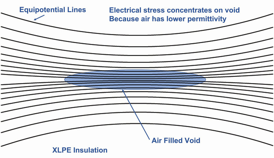
Figure 1: Field Distribution with a Void
TOOLS
Thankfully, partial discharge occurring within the insulation or termination of a cable can be detected with a variety of on-line tests:
- Ultrasonic testing. PD near the surface of a cable termination causes air- and structure-borne ultrasonic energy to be released.
- High-frequency current transformer (HFCT) testing. Partial discharge can induce currents down the shield and the cable conductor at higher frequency than the power signals. By attaching an HFCT to the ground shield of a cable, these signals can be identified and monitored.
- Transient earth voltage (TEV) testing. PD currents cause transient voltage spikes on grounded surfaces such as cable compartment doors and cable sheaths. These can be picked up by measuring for voltage transients on the cabinet doors.
- UHF radio detection. PD causes cable terminations to emit broadband UHF spikes. Outdoor terminations are unshielded, and these emissions can be detected.
Any tool used for cable testing should be capable of multiple techniques and must also be synchronized to the power system frequency for higher selectivity. It must include algorithms to filter and discriminate PD in the presence of noise.
PRACTICAL ISSUES
A variety of issues can limit the ability to find PD in cables, but the two most prominent are access to shield ground straps and conducted noise.
In European-type switchgear, cables are terminated such that the ground straps from the shields are outside the HV compartment. In U.S. ANSI-style switchgear, the straps are entirely inside the HV compartment. This makes application of the HFCT difficult. Permanently installing the HFCT inside the compartment or bringing the grounds straps outside are the most practical solutions. Cables on riser poles are easier since they tend to have exposed grounds.
Noise can play a major role in PD detectability. Highly noisy cables like those attached to inverters or electric arc furnaces can be difficult to test. Temporarily removing the noise source may be necessary. Test equipment has a variety of tools to reduce the impact of noise but there are practical limitations.
LIMITATIONS AND PITFALLS
Additional limitations and potential pitfalls must be considered when running on-line tests.
- The best on-line HFCT test can see only as far as the next point where the shield is grounded. If you have a cable where every splice or manhole location is grounded, you will have to test at each ground location.
- Ideally, you want to test on every ground of each phase conductor separately. Physically, ground connections may make that impossible. A test on the combined ground is possible but it typically has reduced sensitivity. Figure 2 shows a test on a single phase.
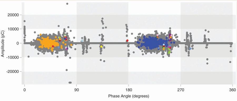
Figure 2: Single-Phase Ground Test — No Filter
Figure 3 shows the same test on combined grounds with no filtering. The noise is much greater and hides the PD on the combined ground.
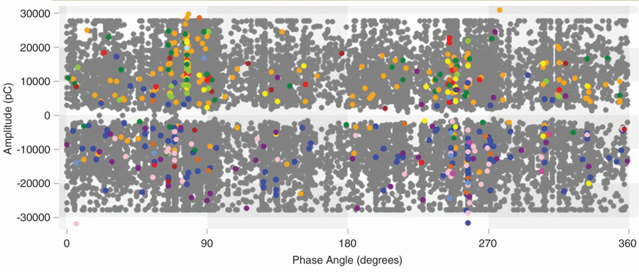
Figure 3: Combined Ground Test — No Filter
Figure 4 shows the same combined test with some noise filtering applied. The PD is visible, but still not as clean as Figure 2.
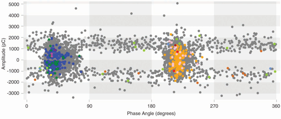
Figure 4: Combined Ground Test with Filtering
TEV testing directly on the sheath of the cable near the termination is a great way to find PD but armored or buried cables can limit the ability to do that test.
Ultrasonic testing of terminations is very useful but well-sealed compartments or outdoor terminations can be a challenge. Contact sensors and ultrasonic dishes can solve these problems.
HFCT testing works well on concentric neutral and tape-shielded cables in good condition. However, if a cable has corrosion in the tape shield overlap, the shield goes from being a continuous, low-impedance path to a long helical coil. This will present higher resistance and much higher impedance to the PD current pulses. This can dramatically shorten the PD detection distance.
CASE STUDY 1
A cable in Saudi Arabia was scanned using an HFCT. Not only was PD present, but the results were so clean the tester could determine the distance to the source. A buried splice was found and confirmed with TEV testing. Once the joint was replaced, the TEV reading showed no PD, confirming the fix. Figure 5 shows the phase-resolved plot and the waveforms that allowed the location to be mapped.
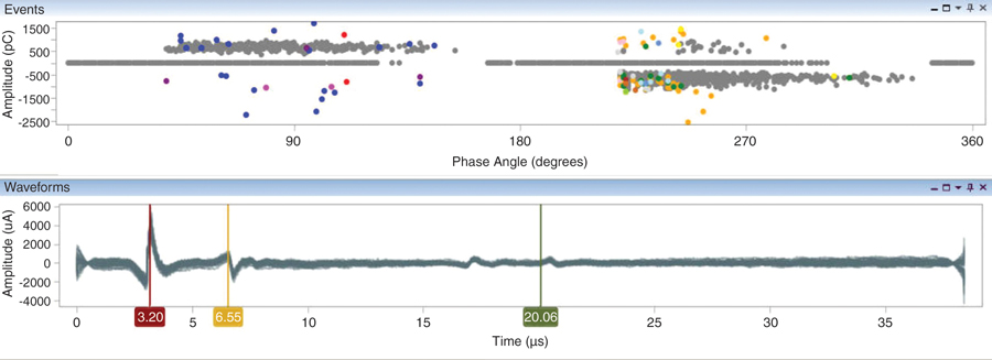
Figure 5: HFCT Results from Defective Buried Joint
CASE STUDY 2
A cable that was only 12 months old was scanned using HFCT and TEV. Where there should have been no PD, there were massive readings. The termination was disassembled and a shield and spring were found to be missing. Once corrected and re-energized, the TEV showed a significant drop in level but the PD was not completely gone. Time to look for more damage! Figure 6 shows HFCT and TEV readings.
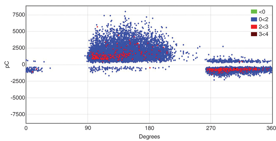
Figure 6: A) HFCT
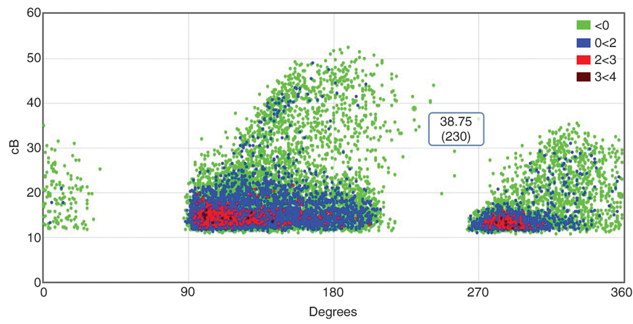
Figure 6: B) TEV Readings of Bad Termination
CASE STUDY 3
A high-voltage asset owner in central Canada has numerous terminations on substation structures. Contamination is building up unevenly on the terminations. This operator is very proactive and periodically does PD surveys of indoor and outdoor assets as part of their regular preventative maintenance.
One of the scanned terminations returned very-high levels of ultrasonic energy. The phase-resolved plots show typical PD results. The source is frequency locked to the power system, and the impulses are occurring twice a cycle, half a cycle apart. The levels are approaching 40 dBuV, which is very high. ANSI/NETA MTS 2019 calls for immediate action on levels greater than 6 dBuV. Figure 7 shows the phase-resolved plot and the contaminated termination.
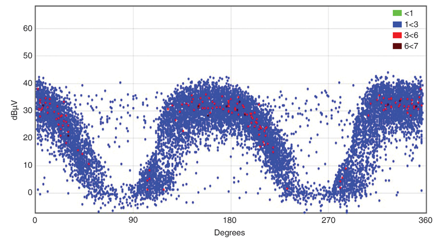
Figure 7: A) Phase-Resolved Plot
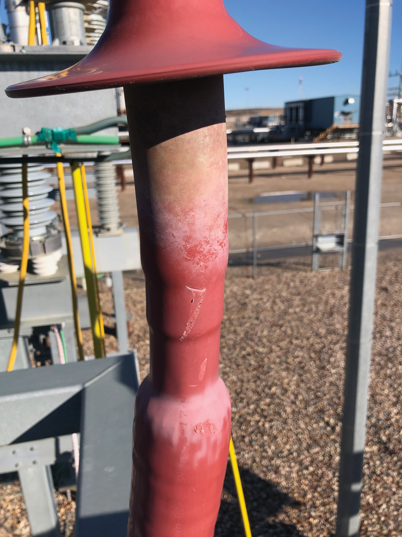
Figure 7: B) Contaminated Termination
During the next scheduled outage, the insulators were cleaned and then rescanned. The ultrasonic energy was gone, proving that the discharge was a result of the contamination. Figure 8 shows the phase-resolved plot and termination after thorough cleaning.
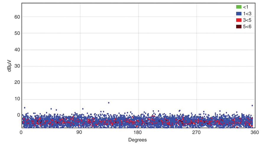
Figure 8: A) Phase-Resolved Plot
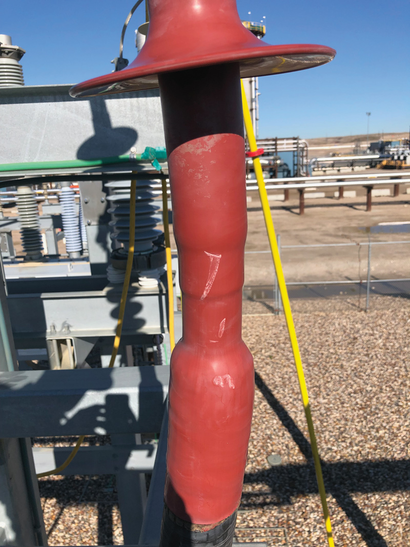
Figure 8: B) Termination After Cleaning
 William G. Higinbotham has been president of EA Technology LLC since 2013. His responsibilities involve general management of the company, including EA Technology activities in North and South America. William is also responsible for sales, service, support, and training on partial discharge instruments and condition-based asset management. He is the author or co-author of several industry papers. Previously, William was Vice President of RFL Electronics Inc.’s Research and Development Engineering Group, where his responsibilities included new product development, manufacturing engineering, and technical support. He is an IEEE Senior Member and is active in the IEEE Power Systems Relaying Committee. He has co-authored a number of IEEE standards in the field of power system protection and communication and holds one patent in this area. William received a BS in computer/electrical engineering from Rutgers, the State University of New Jersey’s School of Engineering, and worked in the biomedical engineering field for five years prior to joining RFL.