

As generation is connected to the grid, the available short-circuit current is evolving, increasing in areas where synchronous resources are installed and decreasing in areas where inverter-based resources, such as solar and wind power, are installed. With the U.S. Department of Energy’s recent plan to drastically increase the amount of solar connected to the grid over the coming decades, one sure fact is that existing and future sites can expect upcoming changes to short-circuit levels.
This has a variety of impacts on the grid, including altering the coordination of installed relays, which is the concern of the three-part NERC PRC-027-1, Coordination of Protection Systems for Performance During Faults that became effective in April 2021.
PRC-027-1 Requirements R1 and R3 relate to the establishment and implementation of a site procedure to ensure coordination is maintained across electrically connected entity boundaries. Requirement R2 requires the reassessment of applicable relay settings against the actual available short-circuit current levels, as opposed to the previously existing — and potentially drastically different — levels used to originally determine the settings. This article dives deeper into each of these three requirements, what they include, and which protective elements are applicable, generally from a generator owner’s perspective.
REQUIREMENT R1
Overview
Requirement R1 itself is composed of three parts, all with the overarching concern of establishing a procedure for developing protection settings while also mitigating the introduction of any potential coordination concerns.
Part 1.1 requires that a procedure be designed for reviewing the data used in short-circuit models for accuracy, so that the model, and therefore the fault levels taken from model simulations, can be the most accurate reflection of the existing system. This ensures that any protection developed using these fault-current levels will be appropriate and effective not only in simulation, but also in the real-world application. The Supplemental Material section of standard PRC-027[1] further elaborates on what this review should include. If a generator owner does not maintain a short-circuit current model, this portion of the standard may require communicating with the transmission planner or other entity that does own the short-circuit model so that the site-specific information can be reviewed.
Part 1.2 requires another review procedure. Once the protection settings of applicable elements have been developed, there should be a systematic procedure to check that they meet technical criteria. No single set of technical criteria is included in the standard, as the criteria is unique for each site depending on protection philosophy, system configuration, and more. Therefore, the technical checkpoints should be outlined by and specific to each entity.
Part 1.3 requires a procedure to communicate settings between electrically connected entities. Four communication procedures are included:
- Communicate proposed settings.
- Respond to connected entities that provide proposed settings and state coordination concerns or confirm coordination.
- Communicate verification of coordination concerns being resolved.
- Communicate updated settings if changes need to be made to those originally communicated due to unforeseen circumstances.
Applicable Elements
Protection elements that are on bulk electric system (BES) elements and that require coordination with electrically connected entities — i.e., have a zone of protection that will overlap with the zone of protection of other elements owned by a separate entity — are applicable to this portion of the standard. For a generator owner, this may include switchyard elements such as distance (21), overcurrent (50/51 or 67 if directional towards transmission system), or differential (87) protections. Phase and ground protections should both be included. Breaker failure (50BF) protection should also be included in communication because, while this protection itself does not need to coordinate with those from other entities, it will affect the coordination timing of the protective elements that will cause it to operate.
A generator owner will also have applicable elements on their step-up transformers and generation, though there are some differences between synchronous and inverter-based resource (IBR) sites.[2] Like the switchyard, distance (21), overcurrent (50/51/51V), and differential (87) protections should be considered and included if their zones of protection extend into zones of protection owned by another entity. Phase and ground protections should be included, as should beaker failure (50BF) protection and negative sequence/unbalanced phase (46) protection. For a synchronous site, protections on the generator bus and generator step-up transformer (GSU) will usually be applicable, except potentially generator differential protection (87G), as it may not extend past the GSU depending on the protection philosophy at the site. In contrast, for an IBR site, protections on the main power transformer (MPT) are usually applicable, while those on the feeders, pad-mount transformers, and inverters do not typically have zones that extend far enough to require coordination with the transmission protections.[2]
Note that the above guidance is based on a typical site configuration and protection philosophy but should not be considered a universal representation. Each site is unique and should carefully consider its specific system and protection schemes to determine which elements require coordination with other entities.
Generally, a generator owner should communicate the protection operating time or characteristic and the settings that will affect this timing to the transmission planner. For distance elements, the settings that determine the reach should also be communicated. The transmission planner may also request additional information in order to assess the coordination.
REQUIREMENT R2
Overview
Requirement R2, the assessment portion of the standard, includes three potential assessment paths.
The first is fairly straightforward; it allows a generator owner to review protective element coordination every six years or sooner. This review should be conducted using fault-current levels from a short-circuit model that has been reviewed and updated as required by Requirement R1.
The second option allows a generator owner to compare fault-current levels from a short-circuit model that has been reviewed and updated as required by Requirement R1 against an established fault-current baseline every six years or sooner. This method potentially avoids a full coordination review if the deviation of the updated fault levels from the baseline is less than 15%. The fault level deviation must be considered at every bus with connected BES elements.
If the updated fault current deviates more than 15% from the baseline, the updated values should be established as the new baseline once a coordination assessment has been performed. The baseline can be updated before this level of deviation has been reached but can only be established after a coordination assessment has been completed.
The third option allows for a combination of the two methods. A site may choose to divide their system so that one portion is assessed using the first option and the other portion uses the second option.
Per PRC-027, fault-current baselines should have been established prior to the standard becoming effective in April 2021. If a site has not established a baseline, the first option is the only path for the first PRC-027 assessment performed. The fault-current baselines can be established after the assessment is completed if the site chooses, and the second or third option could be used for the next PRC-027 assessment in six years or sooner.
Applicable Elements
Similar to Requirement R1, elements that require coordination with electrically connected entities are applicable to Requirement R2 — but only those that are dependent on fault-current levels to develop their settings. This includes phase and ground distance (21) and overcurrent elements (50, 51, 51V, and 67 if directional towards the transmission system).
Note that if a site uses a wye-delta connected transformer with the wye-connected winding on the transmission side, then ground elements on the delta-connected side of the transformer do not need to coordinate with those on the wye-connected side for a fault in the transmission system. This is because the delta-connected winding will trap and circulate zero-sequence currents from the fault on the wye-connected side, effectively isolating the wye-connected and delta-connected zero-sequence systems and eliminating the need for coordination between elements that measure such currents.
Coordination
Requirement R2 is the assessment portion of the standard. It requires existing protection settings to be reviewed to ensure their operation is properly coordinated. What does it mean to be coordinated? There is no one definition, as it is very dependent on protection philosophy, system configuration, breaker operation, etc. Generally, the goal of coordination is to protect equipment and isolate faults while keeping as many pieces of equipment in service as possible. However, how this is implemented from site to site will vary. Coordination for a site with one generator and one transformer will look different than a ring of bus generators which will look different than a wind or solar site.
Regardless of generation type or specific system configuration, identifying the zones of protection of the elements under assessment is crucial to determining coordination. The order of operation of protections will vary from site to site, but the concept of primary and backup elements and protection zones remains applicable.
In protective systems, there are multiple definitions of primary and backup protection. There can be primary and backup protection for the same zone but provided by different types of elements, such as primary differential protection and backup overcurrent protection. There can also be primary and backup protections that perform the same function and provide redundancy in case of mis-operation or equipment failure, as shown in Figure 1 (although redundant protection may be a more appropriate name for such a setup). Additionally, there can be primary and backup protections that have different primary zones of protection, but the backup will operate if the primary does not operate for a fault in its zone after a given time, also shown in Figure 1. This final type of primary and backup protection is the concern of PRC-027 coordination. Elements identified as providing backup protection should typically operate approximately 0.5 seconds after those identified as providing primary protection.[3]
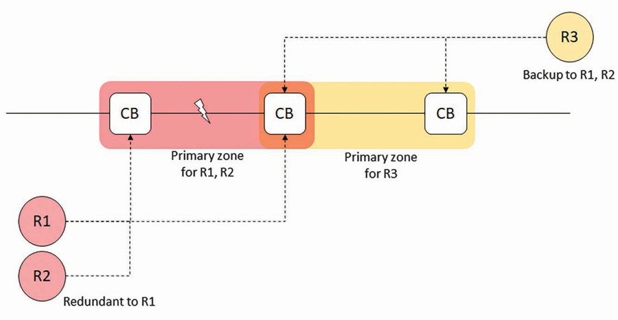
Figure 1: Primary and Backup Protection
To assess coordination, a site should use the actual settings used for the protective elements. This may require pulling the settings from the relay if they are not available. Relay tests can also be used but can be more difficult than relay-specific settings to interpret and use in coordination assessment programs such as SKM Power*Tools, ETAP, ASPEN OneLiner, or other similar software.
REQUIREMENT R3
Overview
The final portion of the standard essentially requires that the processes established in Requirements R1 and Requirement R2 are followed. Following the flow of the established procedure may look something like the following:
- A need for new or revised protection settings has been identified due to adding new protection elements, a mis-operation in an existing element, or another cause. Alternatively, existing settings may have been identified as needing revised settings due to a periodic Requirement R2 coordination review or a deviation of 15% or more from the fault current baseline.
- If the new/revised element is applicable to Requirement R2 (i.e., the settings are developed using fault-current levels and require coordination with other protection systems) or a periodic or fault-current deviation review is being conducted, then the short-circuit model data should be reviewed and updated following the procedure developed per Requirement R1.
a. If the site is using the baseline fault-current option for Requirement R2, the updated fault-current levels may be established as a new baseline as well. - Develop the settings using the appropriate short-circuit levels.
- Conduct a review of the settings following the procedure developed per Requirement R1. This could be a third-party review, a program checker, or some other method as explained in PRC-027-1.[1]
- Communicate the proposed settings and any other necessary information to electrically connected entities following the procedure developed per Requirement R1.
a. If an entity receives proposed settings, they must review the settings and respond, stating either coordination concerns or acceptable coordination.
b. If coordination issues are identified, the entities must work to resolve them to the point possible.
c. Verify resolution once any potential coordination issues are resolved. - If any protection setting changes need to be made to those initially communicated to connected entities, those new settings should be communicated. A change in settings could be required due to implementation issues, mis-operation, or other concerns.
a. As good practice, relay testing and setting documentation should take place as well.
CONCLUSION
This article provided an overview of the PRC-027 requirements, along with some guidance on how to implement them. This is not a comprehensive guide on the standard, however, and implementation will vary from site to site.
Additional recommended reading:
- For further descriptions on the components of PRC-027 and the reasoning behind its criteria: NERC Reliability Standard PRC-027-1 and the Supplemental Material section
- For element applicability: Transmission-to-Generation Protection System Coordination Guidance and Practices, a joint document by the North American Transmission Forum (NATF) and the North American Generator Forum (NAGF)
- For coordination guidance: NERC System Protection and Control Subcommittee. Considerations for Power Plant and Transmission System Protection and Coordination
REFERENCES
[1] NERC Reliability Standard PRC-027-1, Coordination of Protection System Performance During Faults, 2007.
[2] NERC System Protection and Control Subcommittee. Considerations for Power Plant and Transmission System Protection Coordination, Technical Reference Document — Revision 2, July 2015.
[3] NATF, NAGF. Transmission-to-Generation Protection System Coordination Guidance and Practices, Version 0.94, 2020.
 Maysam Radvar, PEng, PE, has been a Senior Power System Engineering Manager for Ready Technologies, a division of Shermco, since 2010. After acquiring a BSEE and MSEE at the University of Alberta, he has established his career in the field of power systems and protection systems. Maysam is interested in performing NERC compliance studies, generator baseline testing, NERC MOD-026 and MOD-027 testing, power system dynamic and transient stability analysis, power system protection design, and renewable energies. He is a Senior Member of the IEEE Power and Energy Society (SMIEEE), the North American Generator Forum (NAGF), and the Western Interconnection Compliance Forum (WICF). He is a Professional Engineer in the states of Washington, Wyoming, Colorado, and Maine, as well as in Alberta, British Columbia, Saskatchewan, and Ontario, Canada.
 Casey Whitt has worked for Ready Technologies, a division of Shermco, since she graduated from Oregon State University in 2019 with a BS in electrical and computer engineering and a minor in computer science. Her current area of focus is assessing NERC compliance, particularly for renewable sites, but she also has interest in renewable energy positive sequence modeling, electromagnetic transient modeling, and protection system design. She is currently working towards her Professional Engineer license.