
Most electrical equipment manufacturers provide life and performance expectancies with their equipment in the form of operation and maintenance manuals. Life expectancy is based on the premise that equipment has been professionally installed, is maintained in accordance with the manufacturer’s guidelines and recommendations, and is being used per the manufacturer’s designed intent. This premise is also noted in NFPA 70 Article 90.1(B):
This Code contains provisions that are considered (the minimum installation requirements) necessary for safety. Compliance therewith and proper maintenance (manufacturers having precedence even over the code) result in an installation that is essentially free from hazard but not necessarily efficient, convenient, or adequate for good service or future expansion of electrical use.
Additionally, federal laws mandate the installation, safe operation, and maintenance of electrical systems. OSHA 1926, Safety and Health Regulations for Construction Subpart K Electrical, addresses everything from approval of the installed equipment through maintenance and inspection of the equipment. Specifically, OSHA 1926.403, General Requirements addresses issues with suitability, examination, mechanical strength, electrical insulation, heating and arcing effects, system classification, and system installation and use.
OSHA’s Hierarchy of Risk provides the three prime causes of electrical failures:
- Equipment. As equipment ages, its components deteriorate over time caused by electrical stresses created under normal operation. Abnormal operation, typically overloading, serves to accelerate the physical stresses placed on the equipment. Failure to properly maintain the equipment and associated systems also causes undue premature equipment failure.
- Environment. The environmental conditions in which equipment is installed and operated is often overlooked. Humidity, suspended airborne contaminants, and corrosives must be considered.
- Employee. The key to employee performance is qualification to perform an assigned task. The qualification standards clearly defined in NFPA 70E, Standard for Electrical Safety in the Workplace are sometimes not met, and this leads to employee error or shortfalls. Training is essential for long-term expectation of successful operational outcomes.
Motor Control Centers
Motor control centers are subject to constant, ever-changing loads. The inrush of starting current during the locked rotor condition and the system’s response to the various torques in coming up to full operating speed have consequences for the supporting distribution system. Any associated wiring will be subject to electrical stresses of transient high-current inrush and subsequent movement that cause physical damage to insulation and loosens terminations due to thermal stressing.
MCCs are often the epicenter of the manufacturing plant, providing power for equipment across the site. Moreover, their vital role often goes unrecognized for extended periods of time because of a buy-and-forget philosophy toward MCCs. It is a common belief that once an MCC is installed, it can be left to run independently, and maintenance is only needed in the instances of equipment failure. This approach to maintaining MCCs leads to downtime and often catastrophic failures that could have been avoided.
The primary issue with this approach is that an MCC fault, such as a starter failure, can lead to major downtime by causing loss of power to, or control of, plant equipment. The outcome of interruptions to production can mean significant financial losses to a business. If onsite system operational documents are not kept up to date or replacement inventory is not readily available, there may be considerable delay in getting plant operations back to full functional status.
Neglecting an MCC for extended periods of time can lead to catastrophic failure, which leaves companies not only with downtime, but also with a sizeable investment to replace the equipment.
Two photos depict the after-effects of an arc flash event within a lineup. The first photo clearly shows that one of the parallel B-phase motor conductors broke free from its termination and fell towards the A-phase connections that initiated the arc flash event.
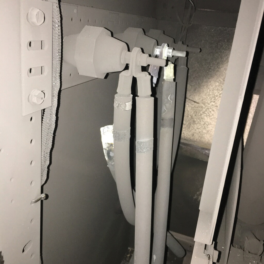
Broken B-Phase Motor Conductor
The second photo shows that the force of the blast was sufficient to blow open the door to the motor connection, the adjacent door where the motor starter contacts and control circuits are located, and the door adjacent and above where the starter fuses and incoming leads are located. Investigation found that the fuses in the motor starter unit immediately upstream failed to clear; the fuses located on an air switch within the metal-clad switch gear finally cleared the fault.
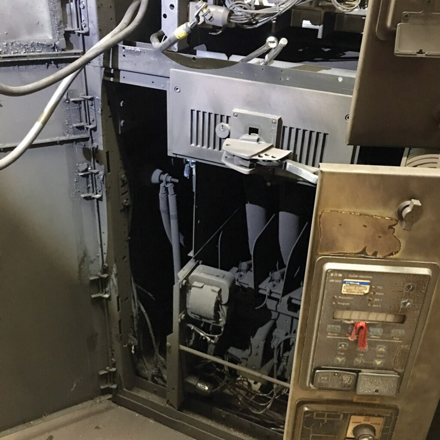
Damage from Arc Flash Event
Infrared scans would have been the primary way to detect this failure ahead of time; however, in this case, infrared windows had not been installed, so no infrared scan could be conducted on any of the lineup.
Safety
MCCs are a common safety concern because operators and maintenance personnel interact closely with the MCC. Recognition of arc flash as a unique electrical hazard has led to a new expectation for circuit protection devices: They must safeguard personnel from the hazards of thermal burns and explosive blasts.
Traditional arc flash mitigation is dependent on single-function circuit protection devices (like fuses) to operate as designed to limit arc flash energy. Unfortunately, overcurrent protection and other components in power system short-circuit protection schemes can fail with no indication that functionality has been compromised until an arc flash event occurs. In such events, the arc flash energy release can be magnitudes greater than expected or calculated. Work methods, tools, and personal protective equipment selected based on predicted energy levels may be insufficient to protect workers within the arc flash zone from injury.
The key to conducting inspection and diagnostics is to remember that the arc flash calculations that may be provided are derived from engineering specifications of clearing times when the overcurrent protection devices were brand new. In all instances, it is important to dress not to a minimum, but to a higher arc hazard level to mitigate the slowing of clearing times created by aging and lack of proper and/or inadequate maintenance. The information provided in NFPA 70E should be considered as a minimum in recommending equipment for personal protection.
Mitigation
So how are these types of events mitigated? The answer is proactive training for qualification, routine periodic and adequate inspection, and maintenance conducted in accordance with the manufacturer’s guidelines and recommendations.
Key players in the manufacturing of MCCs such as Allen-Bradley, Siemens, and Schneider / Square D recommend remarkably similar approaches to conducting inspection and maintenance on MCCs.
To identify the condition of an MCC, maintenance personnel should routinely conduct several checks in accordance with the manufacturer’s guidelines. These can be invasive or non-invasive tasks from simple visual checks to more complex analysis. It is important to conduct checks to establish cleanliness, verify software, and check and back up the operational parameters on programmable logic systems. Records of these parameters must be up to date. Maintenance personnel can conduct visual inspections to look for indications of overheating at terminations and conductor insulation points. In the absence of any direct guidance, NFPA 70B Chapter 16 can be used to initiate a starting point in establishing a basic motor-control maintenance program.
Routine Maintenance
The goal of routine maintenance is to restore the MCC to its original condition. Any components that show signs of wear and tear can be serviced and/or replaced. Common routine maintenance tasks recommended by major manufacturers include:
- Operating mechanism. Check for proper functioning and freedom from sticking or binding. Replace any broken, damaged, or badly worn parts or assemblies. Check all mechanical fastening devices and return to manufacturer’s specified torque values.
- Contacts. Check contacts for excessive wear and dirt accumulation. Discoloration and slight pitting are acceptable. Do not use files to dress contacts. Do not use contact spray cleaners, as they leave a residue that can cause sticking and/or interfere with electrical continuity. Replace contacts only after the silver has become excessively worn. Always replace contacts in complete sets to avoid alignment issues and uneven contact pressure.
- Terminals. Loose connections can cause overheating that can lead to equipment malfunction and failure. Verify the tightness of all terminals and busbar connections to ensure these mechanical fasteners meet the manufacturer’s recommended torque specification. Replace any components or wiring damaged by overheating. Check the grounded conductor, equipment grounding conductor, and grounding electrode conductors for proper termination tightness.
- Coils. If a coil exhibits evidence of overheating (cracked, melted, or discolored insulation), it must be replaced. Check for and correct any detected over- or under-voltage conditions, which can initiate coil failure. Clean any residue of melted coil insulation from all other parts of the device. If it can’t be sufficiently cleaned, it may be necessary to replace those contaminated parts or assemblies as well.
- Pilot lights. Replace any burned-out lamps and/or damaged lenses.
- Solid state devices. Solid state devices require little more than periodic visual checks. Ensure that the printed circuit boards are properly seated in edge connectors. Board-locking devices must be in place. If electrically operated venting is incorporated, verify fan operation and replace any associated filters.
- Locking and interlocking devices. Check proper operating condition and capability to perform intended functions.
- Environment and physical condition. MCCs are often physically located in areas that allow animals to establish habitats; this increases the danger of vermin being present. This can cause damage or even destruction of cabling and terminations. Qualified staff should conduct routine visual inspections on the physical condition of the equipment. Once identified, the situation can be rectified to restore the MCC to its proper operating state.
- Replacements. Make any necessary replacements only with OEM materials. Ensure parts are properly matched to the model, series, and revision level of the equipment.
- Final checkout. After maintenance or repair of industrial controls, always test the control system for proper functional operation under controlled conditions that avoid any hazards associated with a control malfunction.
Conclusion
As is often the case when a breakdown occurs, maintenance personnel commonly employ quick-fix remedies to restore operations as quickly as possible. If previous maintenance was done as a quick fix, this must be addressed by restoring everything to the manufacturer’s specifications at the earliest possible time. This maintenance aims to restore the MCC to its original condition. If any components show signs of wear and tear, these can be serviced and or replaced, as necessary.
References
AVO Training Institute. Electrical Safety Text.
National Fire Protection Association. NFPA 70, National Electrical Code, 2020 Edition.
National Fire Protection Association. NFPA 70B, Recommended Practice for Electrical Equipment Maintenance, 2019 Edition.
National Fire Protection Association. NFPA 70E, Standard for Electrical Safety in the Workplace, 2018 Edition.
Occupational Safety and Health Administration. OSHA 1926.403 CFR, General Requirements.
Allen-Bradley. Preventive Maintenance Checklist of Industrial Control and Drive System Equipment. December 1999.
Accessed at DRIVES-TD001A-EN-P.pdf
www.rockwellautomation.com.
 Rodrick J. Van Wart is a Senior Consultant and Instructor at AVO Training in Dallas, Texas, and an Instructor at the Omega Institute for Continuing Education. He has over 47 years of experience in the electrical industry that includes chairing test development for the International Code Council’s exams for inspectors, overseeing development of Iowa’s electrical licensing and permitting programs, and providing training for the state’s Electrical Examining Board members and support staff. Rod served several municipalities as an electrical and mechanical inspector, earned Public Management certification from Drake University, and is a Certified Building Official. A subject matter expert in adult learning precepts and instruction in a classroom setting, he designed and implemented new core curriculum subject matter and has been awarded Top Gun status at Mike Holt’s Instructor Training Conference. During his four years in the United States Navy, Rod certified apprentices and third-class nuclear electricians logging 336,800 hours of total student contact time. He currently serves as a member of the IEEE PES/ESSB Committee on Working Groups 450, 484 (Vice Chair), 485, 1188, 1578, and 1679.