

Circuit breakers are indispensable in any electrical power system. They are the only piece of equipment that can switch not only under normal load, but also under fault conditions. They must be able to reliably disconnect a faulty section from the grid as quickly as possible. Circuit breakers must be able to meet this requirement even after they have been in service for a long time. Their reliability is essential for the prevention of consequential power system failures and the safety of the electrical power supply.
Typical tests include measuring operating times and static contact resistance. A more extensive condition assessment is possible when further measurements, such as motion/contact travel measurements or measurement of the motor current signature, are performed. For circuit breakers that are equipped with an under-voltage release or an over-current release, testing these features further increases the available information that can be used during the condition assessment of the circuit breaker.
MEDIUM-VOLTAGE CIRCUIT BREAKERS
While old medium-voltage circuit breakers often used oil as the interrupting medium, in modern times, vacuum is the preferred medium and is thus used almost exclusively. Essential elements of a breaker include the interrupter unit, the mechanical linkage, and the operating mechanism with an energy storage system. The energy that is needed to operate a circuit breaker is high, and it must be made available within a few milliseconds — almost instantaneously. Springs are used in most cases because they are simple in comparison and very reliable at the same time. Two separate springs allow the energy for the opening and the closing operation to be stored. In order to release the energy that is stored in the springs, two coils are needed to control the springs remotely. The opening spring is charged during the closing operation of the breaker, and the closing spring is charged by a motor.
TESTING MEDIUM-VOLTAGE CIRCUIT BREAKERS
Following is a brief overview of the most important medium-voltage circuit breaker measurement methods.
Off-Service Measurement Methods
- Timing. Timing measurements according to IEC 62271-100[1] are used to determine operation time and are part of the most common tests. The timing test uses a resistance or voltage threshold to determine the state of the main contacts.
- Static contact resistance. Verifies whether the resistance of the main contacts allows the current to flow with low losses.
- Dynamic contact resistance. Records the contact resistance during the operation of the breaker and delivers information about wear-related problems with main and arcing contacts, while also determining timing results.
- Motion/contact travel. Verifies operating mechanism and mechanical linkage and indicates potential mechanical wear.
- Coil current. Records the current signature curve of the command coils during breaker operation during a timing test. Deviations show possible electrical or mechanical defects of the trip or close control components. According to the IEC, the trip coil shall work between 70% and 110% of nominal voltage, and the close coil shall work between 85% and 110% of nominal voltage.
- Motor current. The motor current analysis records the inrush and steady-state currents as well as the spring charging time. According to the IEC, the motor shall work between 85% and 110% of nominal voltage.
- Minimum pick-up. Determines the minimum voltage necessary to trip and close the breaker and verifies whether it can reliably operate in the event of a low DC supply.
- Under-voltage release test. Determines the trip voltage of the under-voltage coil.
- Over-current release test. Used to determine the current that trips the breaker. Over-current releases are commonly used together with self-powered over-current protection relays.
In-Service Measurement Methods
- First-trip test. The first trip test is carried out while the breaker is still in service and has been in service for a long time. Connections are made at the trip coil and at the CT’s secondary side. The opening times are measured by monitoring secondary current of the CTs.
- Voltage-based timing measurement (VTM). VTM is the only measurement method available to measure the timing of a medium-voltage GIS, since the main contacts are sealed and cannot be accessed. It can be applied to all circuit breakers with a voltage detection system (VDS) that makes the main voltages accessible.
UNDER-VOLTAGE RELEASE
Purpose of Under-Voltage Release
Circuit breakers are equipped with an under-voltage release if the related protection system has no supply voltage backup, for example, if a protection relay is powered by a battery, but the battery voltage is not monitored. If the battery voltage falls below 70% of its nominal voltage (see IEC 62271-1:2017[2] for details) so it is no longer able to operate the protection relay, any failure (e.g., an over-current) would no longer be discovered. The under-voltage release is often found in industry grids, as it is a relatively cheap solution to make sure the breaker is opened when a battery failure occurs.
An under-voltage release may operate when supply voltage is between 35% and 70% of the nominal voltage and must operate when the supply voltage drops below 35%. In addition, the under-voltage release prevents closing when the release has operated, such as after opening the circuit breaker.
Under-Voltage Release Test
The under-voltage coil is supplied, after which the breaker is closed. Then the voltage is ramped down in steps from the nominal voltage until the under-voltage release trips (Figure 1). This is the trip voltage.
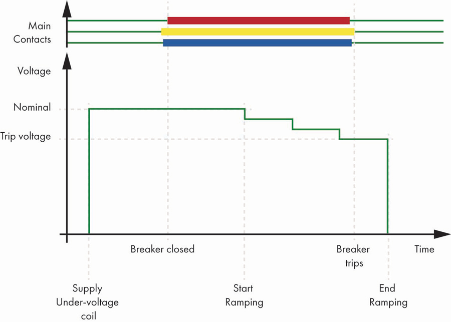
Figure 1: Under-Voltage Release Test Signal
OVER-CURRENT RELEASE
Purpose of Over-Current Releases
Current transformer releases are used on circuit breakers in substations where no grid-independent supply voltage is available. These are low-cost stations with basic functionality. Quite often, they do not have any remote-control features, and the breakers do not have a close coil. Such substations are common in distribution grids where the downstream infrastructure is not critical, such as in residential areas.
Over-current releases are activated by a current. The current comes from the tripping transformer, which usually has a nominal value of 0.5, 1.0, or 5 A AC. An over-current relay feeds the current flow from the tripping transformer to the circuit breaker. The tripping transformer and the over-current relay (self-powered over-current relay) are usually powered by the secondary side of the CTs. In the event of an over-current, the relay switches the current of the tripping transformer to the circuit breaker; this causes it to open the main contacts and isolate the faulty grid part.
Over-Current Release Test
With the breaker in closed position, a current is ramped up in steps until the breaker trips (Figure 2). This is the trip current.
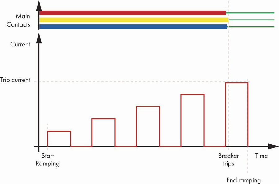
Figure 2: Over-Current Release Test Signal
Other Designations
- IEC 62271-100: Indirect current release
- ABB: Transformer operated release
- Siemens: Current transformer operated release
- Also in use: Indirect over-current release
CLOSING TIME CALCULATION FOR CIRCUIT BREAKERS WITHOUT A CLOSE COIL
All breakers should have at least a trip coil so that faults can be isolated. Some old breakers or breakers with over-current release do not have a close coil. These breakers are closed manually.
According to IEC 62271-100,[1] closing time is the elapsed time from the moment the close coil is energized until the contacts touch all poles (Figure 3).
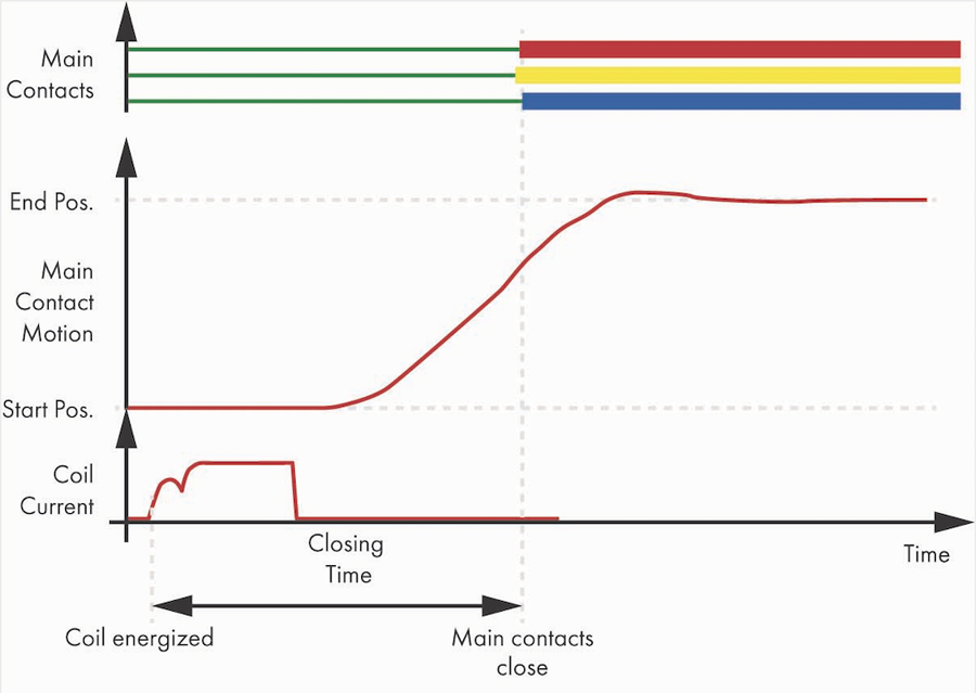
Figure 3: Closing Time Calculation According to IEC 62271-100[1]
For circuit breakers without a close coil, the closing time calculation according to the IEC standard cannot be applied. Therefore, an alternative approach must be used. The closing time can be the time when the circuit breaker main contacts begin to move until the contacts touch all poles (Figure 4).
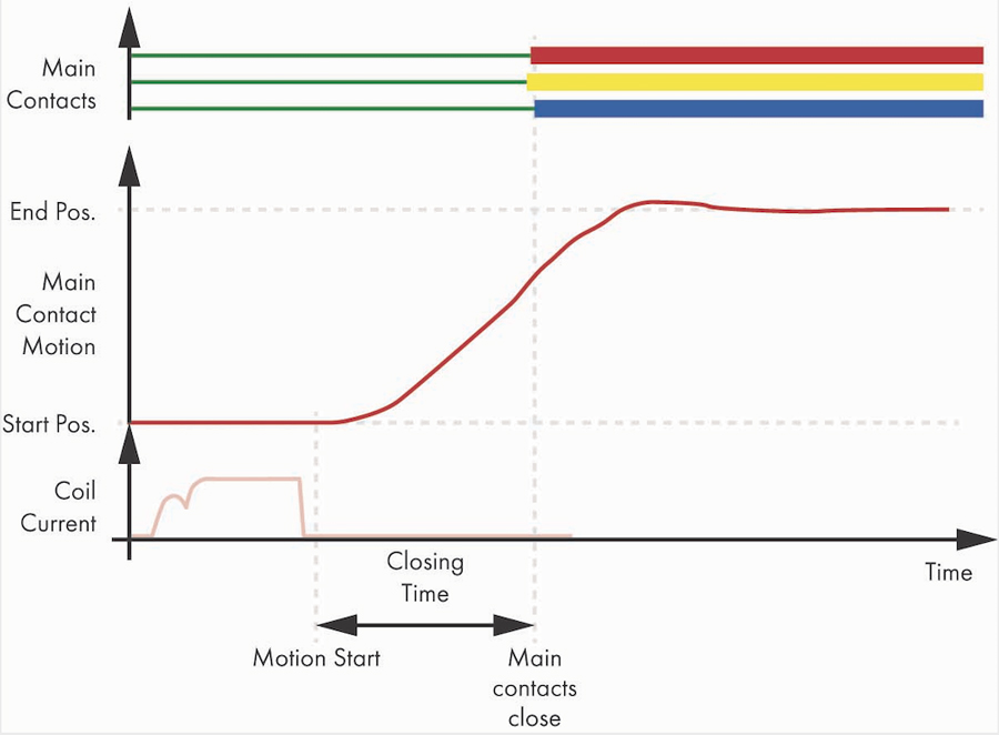
Figure 4: Closing Time with Motion/Contact Travel as Start Reference
REFERENCES
[1] IEC 62271-100
[2] IEC 62271-1:2017
 Siegfried Bernhauser has worked for OMICRON electronics in Klaus, Austria, for more than 25 years. After starting as a Technical Writer, he worked as a Marketing Communications Engineer with a focus on business-to-business communication for power system testing products such as the CMC 356, the CPC 100, the CT Analyzer, the TESTRANO 600, the MPD 800, and the CIBANO 500. Most recently, he focused on producing switchgear testing videos. Siegfried studied TV and film production at the Danube University Krems, Austria.
 Ari Tirroniemi has worked for OMICRON electronics in Klaus, Austria, for more than 15 years as a firmware developer and later as Project Manager for products such as DIRANA and CIBANO 500. He is currently an Application Engineer focusing on circuit breaker testing. Ari studied applied physics and electrical engineering at the Linköping University of Technology, Sweden.