
Partial discharge (PD) testing is a form of diagnostic testing for power cable systems. PD testing of medium- and high-voltage cable applications is beneficial when paired with other cable tests including very-low frequency (VLF) and tan delta (TD) tests. Partial discharge testing is another way to judge a cable’s insulation vitality or ability to endure electrical stress. Utilizing PD as an off-line testing technique can identify problematic defects long before a fault situation would create an in-service outage.
In addition to using partial discharge testing for condition-based maintenance testing for aged cables, it can be used for acceptance testing and commissioning. It is possible to considerably reduce the costs of maintenance and network renewal with the help of cable diagnostic techniques. More informed decisions eliminate unnecessary cable repairs or renewals, which leads to an increase in a cable’s life expectancy. Conducting a PD test during commissioning and acceptance can help find defects before the cable is placed in service, which will also increase reliability and verify the workmanship of the cable installation.
Another means of locating PD is continuous on-line monitoring, which can be established to provide advanced warning that a cable’s insulation is deteriorating while in service. Off-line PD resolves many of on-line PD’s limitations; however, this method requires the cable to be de-energized and removed from service during a scheduled outage. It can also be used as a quality check in a forced outage situation after repairs are performed and before the cable is placed back into service.
OFF-LINE PD TESTING
When using off-line PD testing, a separate power supply is coupled to the cable under test. Thus, the PD test can be accomplished at various levels of rated voltage (Uo) from 0.5 to 1.7 times on aged cables and up to 2 times on new cables. Uo refers to the voltage magnitude as a multiple of the rated operating voltage in reference to the phase to ground voltage. PD should not occur below the operating voltage of the cable. Before testing can commence, a calibration measurement must be conducted using a known apparent charge, typically starting at 1 nC (nanocoulomb). The coulomb magnitude can be adjusted to determine a suitable bandwidth, which is dependent on the overall length of the cable. This ensures reproducible measurements and a reliable evaluation of comparable data.
A disturbance level or background noise measurement should also be taken to give a baseline of the PD measuring circuit. The partial discharge testing procedure should start at 0.5 times Uo and rise by 0.1 to 0.2 until PD is discovered. This is referred to as the partial discharge inception voltage (PDIV). If the PDIV is close to operating voltage or Uo, this would cause immediate concern for replacement or repair, as necessary. Once the PDIV is achieved, the voltage should be decreased until the partial discharge has been extinguished, known as PDEV. The measurement of PDEV is critical as it will determine whether partial discharge will occur on the cable under normal operating conditions if an over-voltage condition arises, thus leading to the situation where PD activity is continuously working to degrade the cable’s insulation. The effects can only be reversed if the cable is de-energized and returned to service.
In contrast, if the cables do not display PD up to the maximum applied voltage, the testing can be increased to ensure no partial discharges occur. If PD has begun at a lower interval of 1.1 or 1.2 Uo, the specimen can be placed in service, but the critical state must be noted for future replacement or repairs.
PD testing requires an AC waveform to function, for example, power frequency (60 Hz, 50 Hz) or very-low-frequency (VLF). Various VLF waveforms are used in cable testing, including VLF sinusoidal, VLF cosine rectangular (CR), and damped ac (DAC). VLF sinusoidal and cosine rectangular are continuous waveforms, while DAC is a decaying waveform consisting of discreet pulses that may have significant time between pulses on longer cables due to the increased capacitive load.
PARTIAL DISCHARGE IN CABLES
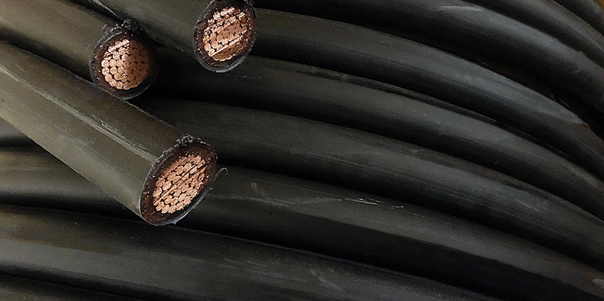
The measurement of partial discharge (PD) activity is a diagnostic method used to evaluate insulation quality. These measurements can be performed on cables, switchgear, transformers, or other types of electrical power equipment. Partial discharges are localized electrical discharges or sparks that can occur between conductors, such as the conductor and metallic sheath of a typical power cable (Figure 1), when the electrical insulation begins to deteriorate. However, these defects are not severe enough to bridge the insulation material to cause a short circuit condition to fail the cable.
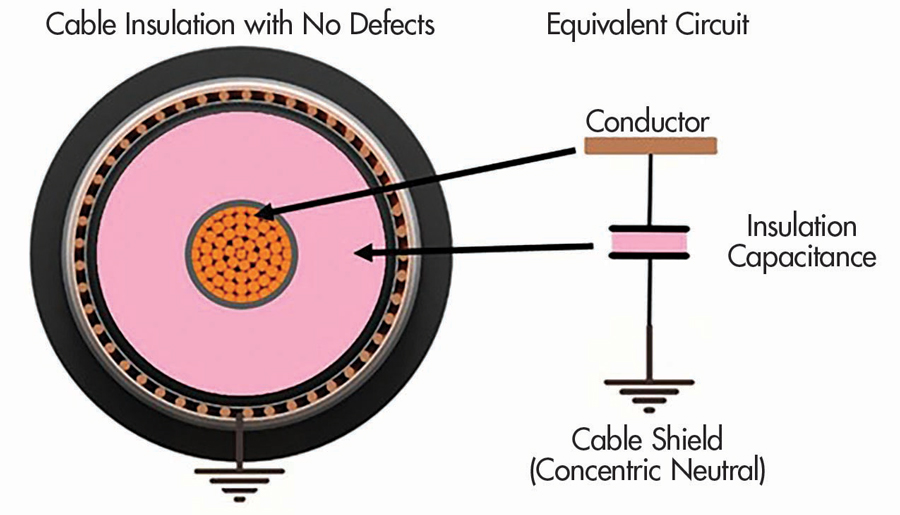
Figure 1: Typical Shielded Cable Construction
PD activity is typically the first indicator of insulation deterioration within an insulation system. This is especially true for cables and cable joints (splices) where 89% and 91% of failures, respectively, are attributed to breakdown of the insulation per IEEE Gold Book, Table 36. The measurement of this activity can be analyzed to determine the type, magnitude, location, and applied voltage. These results can be used to “predict with a high level of confidence that a given cable is in very poor condition and is likely to fail in the near future.” (IEEE 400.3)
CABLE DEFECTS
Three types of defects are typically found in power cables: void, surface, and corona discharges.
Void discharges (Figure 2) occur when a cavity is present in solid insulation.
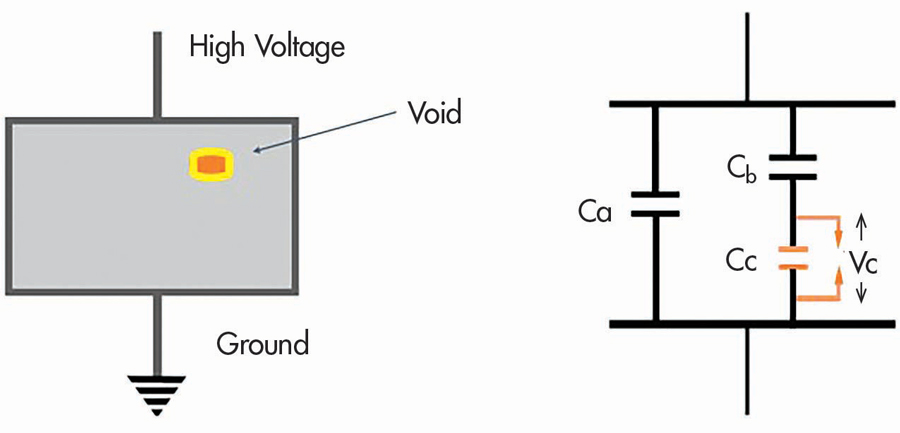
Figure 2: Equivalent Circuit of Dielectric with Void
Surface discharges (Figure 3) are seen when PD events occur on the surface or interfaces of surfaces where there is physical damage. While there are many sources of surface PD, some examples are deep cuts where two layers of a cable meet due to poor workmanship such as on the semiconducting and insulating layers or improper positioning of stress relief at a termination or splice.
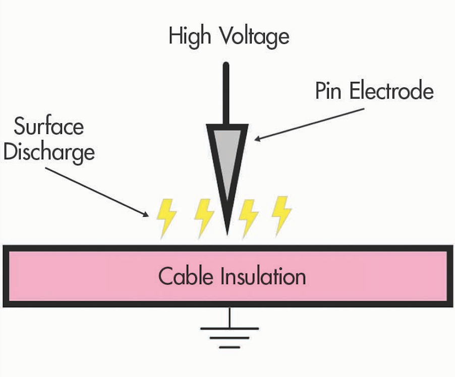
Figure 3: Surface Discharge
Corona discharges (Figure 4) occur when the electrical field of an energized conductor exceeds the dielectric strength of a gas creating a partial discharge. These types of discharges can be seen in a cable where sharp edges exist due to workmanship errors while installing a termination or splice. Another instance where a cable may experience corona discharges is in an air-filled void. In this case, the electrical stress will cause partial discharges across the air within the void.
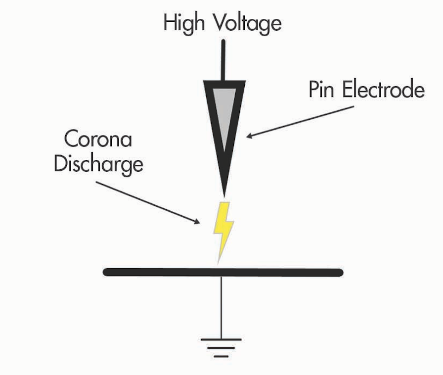
Figure 4: Corona Discharge Model
These deformities can exist for many reasons (Figure 5). However, they usually form when existing water trees convert to conductive electrical trees and begin to destroy a cable’s insulation.
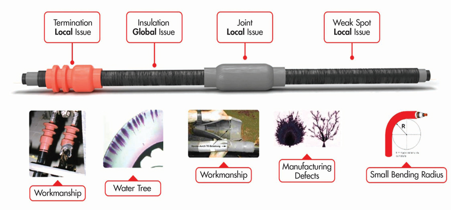
Figure 5: Common Cable Defects
The difference of potential within the void causes a point of concentrated electrical stress (Figure 6) that will continually deteriorate the dielectric strength of the insulation until it reaches total failure.
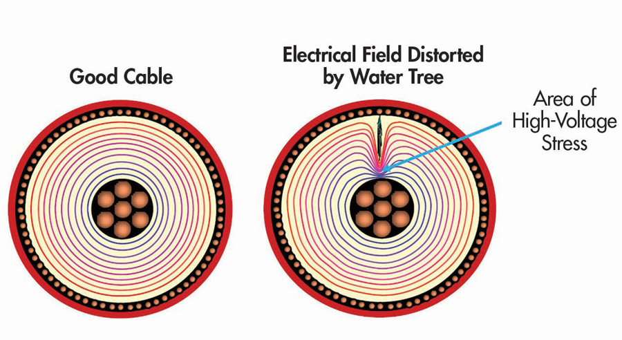
Figure 6: Electrical Field Distribution
APPLIED WAVEFORMS FOR PD MEASUREMENTS
Utilizing these off-line PD wave shapes for testing the VLF sinusoidal waveform can also be used as an initial wave shape for finding PD.
VLF Sinusoidal
VLF sinusoidal imitates the same wave shape as line frequency (50 Hz, 60 Hz), having rms and peak voltages; however, it is slowed down to 0.1 Hz. This waveform is recognized for VLF withstand testing per IEEE 400.2. VLF sinusoidal is a prolonged changing wave that takes 10,000 ms or 10 seconds to produce one entire cycle or a polarity crossover every 5,000 ms (about 5 seconds).
VLF Cosine Rectangular
A more advanced form of PD testing requires VLF cosine rectangular (CR) to be comparable to VLF sinusoidal. However, it does not have a rms voltage; instead, it only uses peak voltage. It may look identical to a square wave, but it is not a simple square wave. CR maintains a 5-second DC hold followed by a sinusoidal transition into a 5-second hold of the opposite DC polarity. These back-and-forth transitions continue for the entirety of the test. The DC holds for a very short time and does not damage the cable’s insulation as continuous DC testing does because the polarity interval is brief, thus emulating an AC sinewave with only 5 seconds +/- peak voltages.
During PD testing, the CR transition uses the cable’s capacitance and a fixed inductor within the test equipment to create a resonance circuit. When the polarity transitions occur, the circuit resonates one-half cycle applying a diode to stop the polarity switch. VLF cosine rectangular polarity reversal is in the range of 16 ms to 1.6 ms, being similar to the polarity crossover of 60 Hz at 8.3 ms or 50 Hz at 10 ms. It therefore produces a considerably closer transition to line frequency than 5,000 ms (about 5 seconds) VLF sinusoidal waveform that is 1,000 times slower.
Damped AC
Another advanced technique is damped AC, which sets up a resonance circuit similar to CR. However, DAC allows the voltage to exponentially decay through resistive losses of the circuit. It gives DAC a frequency closer to that of line frequency range (30 to 300 hz). The greater the frequency, the greater the probability that PD could be measured and the lower the PDIV can be. The voltage that is produced is only on the cable for a very short duration and uses a fluctuating waveform for only a few hundred milliseconds, making DAC the gentlest waveform for off-line PD testing of cables. VLF cosine rectangular and damped AC have polarity changes closer to line frequency than VLF sinusoidal. This increases the likelihood of finding PD in the cable. Solely utilizing VLF sinusoidal for PD testing may not represent the actual condition of the cable when testing.
PDIV and PDEV
Partial discharge inception voltage (PDIV) is the voltage at which partial discharge activity begins to occur within a defect. PDIV is found by slowly raising the test voltage until PD activity is seen at any point along the cable, whether it be mid-span, a termination, or a splice point. This information is critical to understanding the quality of a cable’s insulation. As of this article, the PDIV thresholds established by U.S. standards do not provide criteria for partial discharge field measurements of in-service cables. Despite the absence of this criteria, this value should be measured and recorded to compare to future field measurements. Reduced PDIV in comparison to previous tests should be followed by further investigation to determine the insulation quality of a cable.
Partial discharge extinguish voltage (PDEV) is the voltage level at which PD activity is no longer active in the test specimen. This is determined by gradually lowering the applied voltage once PDIV is discovered to a voltage magnitude where partial discharges are not measured. As with PDIV, field testing criteria has not been established per U.S. standards; however, it is important to note the applied voltage at the point of PDEV. Although established thresholds are not provided for field testing, the PDEV values set forth for factory testing can be used to make general decisions regarding the condition of power cables. For separable connectors (IEEE 386), partial discharge activity should extinguish at 1.3 times above the rated voltage of the cable. Respectively, for cable joints (IEEE 404) and terminations (IEEE 48), the PDEV threshold is 1.5 times the cable’s rated voltage.
PARTIAL DISCHARGE ACTIVITY CHARACTERISTICS
Localization
Localization (Figure 7) is a valuable benefit to partial discharge testing. This can help determine the distance and location to a source of partial discharge in a cable.
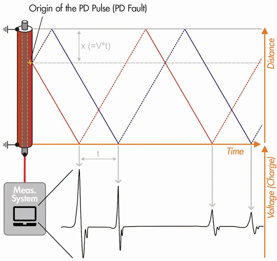
Figure 7: Partial Discharge Localization Measurement
PD Localization Mapping
PD localization mapping (Figure 8) gives the engineer or technician a visual indication of the distance to a defect and the discharge magnitude. These results can be compared to the physical layout of the cable to help pinpoint weak areas of a cable.
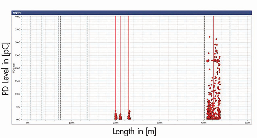
Figure 8: Localization Map of Partial Discharge
The test set-up prior to taking any measurements is a key component to ensuring the distance found in the test results is accurate. The velocity factor or propagation of velocity must be properly selected for the type of cable being tested.
PD Activity Magnitude
Partial discharge magnitude is measured in coulombs. This is typically found in the range of picocoulombs (pC) or nanocoulombs (nC). Generally, any measurement seen above 100 pC is considered a cause for concern. However, this is dependent upon other factors, such as the insulation type of the cable being tested, the service age of the cable, and environmental conditions at the time of the test. Results of elevated partial discharge levels should be followed by further investigation to determine the source of the PD activity. The benefit of partial discharge testing is maximized when included with other types of cable tests as a part of a cable maintenance program.
Benefits and Limitations
One of the greatest benefits of measuring partial discharge on cables is the ability to make maintenance decisions based on the actual condition of the cable. The presence of PD activity will be the first indication of deterioration of the insulation system within a cable. This allows the end user to address these problems before the cable reaches the point of total failure. This can help avoid unexpected system outages, thus improving cable reliability.
Another significant benefit of partial discharge testing on cables is the localization of cable defects. Analysis of the results allows the engineer or technician to determine a specific source of PD activity within a cable, such as a termination or cable joint (splice). Cable defects are located through generated high-frequency pulses that are propagated in both directions. During the measurement, the system uses the incoming signals to identify the directly incoming PD pulses and the respective reflections, as was seen in Figure 7.
Cable age and neutral conductor condition are two characteristics that may significantly affect the ability to localize PD activity on a cable. Damaged or corroded neutral conductors could make it exceedingly difficult or impossible to properly localize PD activity within a cable. In cases where the user has difficulty localizing the source of partial discharges, the neutral conductor should be inspected and tested.
One specific example of an application that creates a major challenge for localization is tape-shielded cables. As these types of cables age, corrosion forms between half-overlapped spiraling conductive layers. The presence of this oxidation creates an attenuating effect that interferes with the high-frequency pulses applied to localize the PD activity.
CONCLUSION
There are numerous choices for the frequency and waveform that is applied during an off-line partial discharge test. Testing at a power frequency of 50 or 60 Hz matches operating conditions, but this requires an exceptionally large power supply and is not practical for most field conditions. Testing at lower frequencies such as 0.1 Hz reduces the need for using a large power supply and allows the use of a much smaller, field-friendly unit. Testing can be accomplished utilizing sinusoidal, cosine-rectangular, or damped AC waveforms. The choice of cosine-rectangular or damped AC more closely replicates testing at power frequency. These frequencies are experienced during the polarity changes that take place throughout the test where the change in voltage with respect to time occurs at a rate similar to power frequency. Therefore, testing with cosine-rectangular or damped AC provides the benefit of a smaller test unit while still sustaining the means for an effective measurement.
REFERENCES
[1] IEEE. IEEE Std. 493-1997, IEEE Recommended Practice for the Design of Reliable Industrial and Commercial Power Systems (Gold Book), pp.1-464, 31 August 1998, doi: 10.1109/IEEESTD.1998.89291.
[2] D. Gowda and A. Desai. “Modeling of Partial Discharge (PD) for Solid Insulation with Void and Building a Hardware Setup to Measure Partial Discharge,” Biennial International Conference on Power and Energy Systems: Towards Sustainable Energy, 2016.
[3] “Guidelines to Perform On-Line Partial Discharge Measurements in Underground Power Cable,” Rugged Monitoring. Accessed 22-Sep-2022 at: https://www.ruggedmonitoring.com/blog/guidelines-to-perform-on-line-partial-discharge-measurements-in-underground-power-cable/5e58add9cde096000141a77e.
[4] J. Perkel and J. C. Hernandez-Mejia. NEETRAC, Atlanta, GA, 2016.
[5] D. Götz, F. Petzold, H. Putter, S. Markalous, and M. Stephan. “Localized PRPD Pattern for Defect Recognition on MV and HV Cables,” 2016 IEEE/PES Transmission and Distribution Conference and Exposition (T&D), 2016, pp. 1-4, doi: 10.1109/TDC.2016.752005.
 Jason Aaron has been an Applications Engineer with Megger’s Technical Support Group since 2020. He enlisted in the US Marine Corp right after high school and was trained as an Aircraft Technician. After 10 years of service, he worked for Shermco for 8 years performing start-up, maintenance, and commissioning of electrical power systems and substations while earning Level 4 NETA certification. He is an IEEE member focusing in the areas of circuit breaker primary current injection techniques and cable testing, diagnostics, and fault location.
 Joseph Aguirre is an Application Engineer at Megger. He specializes in cable testing, diagnostics, and fault location techniques as well as testing of all substation apparatus. Joseph trains end users on the theory and proper use of various pieces of high-voltage testing equipment. He has worked as a maintenance technician, a crew foreman for utility substation maintenance and construction, and as a NETA Certified Technician providing commissioning and maintenance on all substation apparatus and industrial electrical equipment before joining Megger. Joseph earned a BS in industrial technology at the University of Texas Permian Basin and is working toward a graduate degree in energy business and an MBA.