

AES personnel were dispatched to a gas plant in northern Alberta, Canada, for emergency repair of a failed 600 v MCC bus. Before the technicians arrived, the 600 v bus components had already been disassembled by facility personnel to prepare for installation of a new MCC section. For our client, getting the facility back up and running was more critical than performing an in-depth investigation.
However, using information and photographs available to us, the technicians explored potential root causes. Moisture, humidity, and condensation were discussed but quickly ruled out due to a functional climate-control unit in the building and the inherently low relative humidity of this area.
Figure 1 shows that the A-phase bus experienced a high degree of heating between the vertical bus connection and the adjacent horizontal bus connection where the eventual failure occurred. This is apparent due to the high level of oxidation on the bus bar and the lack of tin plating.
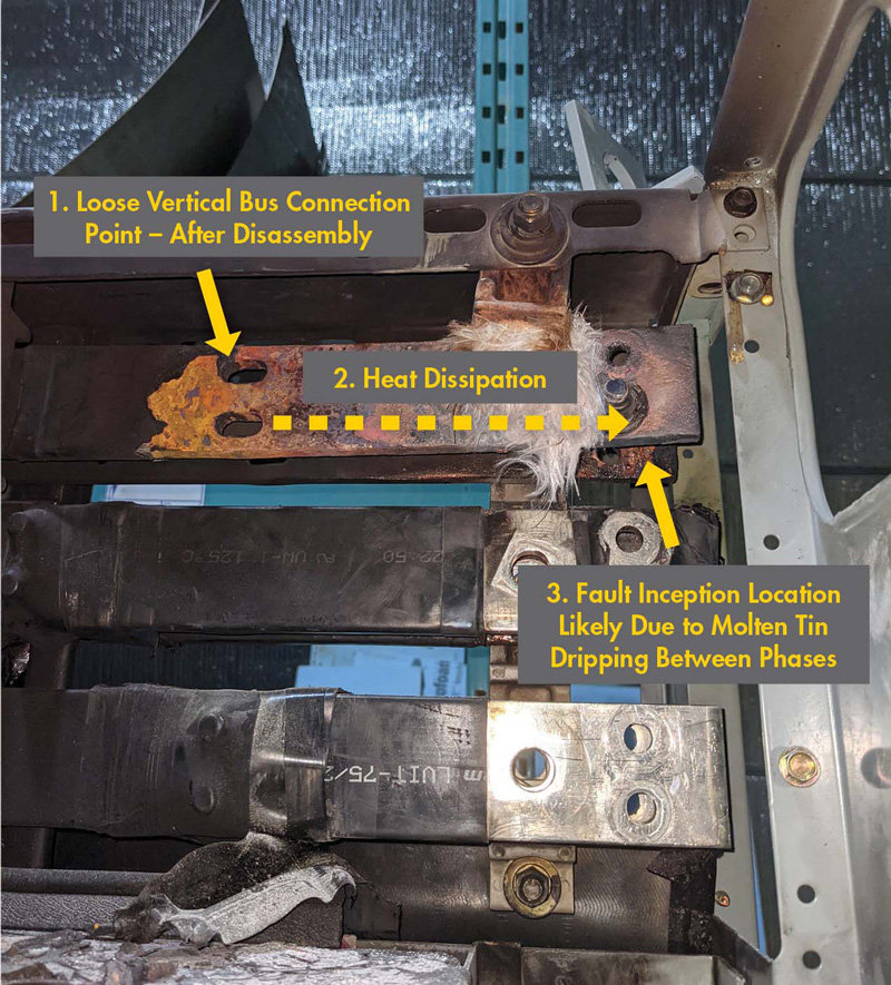
Figure 1: Clues to Root Cause
A loose vertical bus connection would have dissipated heat into the nearby horizontal connection that was thermally and electrically insulated with vinyl tape. This allowed heat to accumulate within this portion of the bus.
At this point, the A-phase bus bar got hot enough to allow the tin plating to melt and molten tin to drip down on top of the adjacent B-phase bus. This would have effectively created a conductive path between phases allowing subsequent ionization of surrounding air and a flash-over arc (Figure 2).
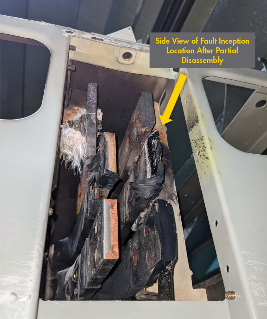
Figure 2: Fault Inception Location
The root cause of this failure was eventually determined to be loose vertical bus connections that were not recognized during the initial commissioning three years prior. As part of our own internal investigation, we asked the client for previous maintenance records on the failed equipment. The client stated that no previous maintenance had been completed. We determined this to be a key contributor to the failure. This deficiency might have been recognized prior to the eventual catastrophic failure if contact resistance testing had been performed during maintenance.
LESSON LEARNED
The catastrophic failure of the 600 v MCC could have been mitigated and potentially avoided during commissioning or maintenance activities by employing several procedures and tools that are available to us as testing technicians:
- Check the torque on all bolted connections if possible.
- Use a higher current contact resistance testing, if possible, within rated equipment capacity (i.e., a 400 A primary-injection test system vs. a 10 A hand-held contact resistance test set).
- Ensure all vertical bus connections were tested by removing bottom-mounted MCC cells. Removing higher mounted cells would suffice if it’s the only possible way, although most vertical bus sections only have a single bolted connection at the top or middle, so testing at any point would confirm the state of the connection. Going to the ends of the bus is always a better test where applicable.
- Visually inspect the bus where accessible to identify anomalies such as insulating tape or clear plastic wrap trapped under the connection or a layer of corrosion/dirt/oxidation inside the connection.
RECOMMENDED TESTS
When testing bolted electrical connections, several additional test procedures are recommended:
- All bolted electrical connections should be tested with a contact-resistance tester. NETA’s recommended current value is 100 A DC; however, if a higher available test current falls under the confines of the equipment’s rated capacity, it should be used because some high-resistance connections don’t manifest until higher current levels.
- If dealing with a 4,000 A bus, consider using a higher-output test unit and more diligently checking the torque on all bolted connections.
- Inversely, if the equipment is only rated for 20 A, for example, a 10 A test can be used if torque cannot be confirmed.
- Torque checks should always supplement testing if the connections are easily accessible. Specific items to be considered for testing include:
- Vertical bus connections usually accessed by temporarily removing MCC buckets
- Grounding provisions such as Pfisterer ground balls
- Higher-current disconnect switches and breakers (refer to ANSI/NETA ATS and ANSI/NETA MTS for more information)
- Fuse connections (connection only), but be cautious when performing contact resistance around a fuse. A low-current test unit or multimeter can be used if fuse integrity needs to be confirmed.
THEORY
Simply put, a high-resistance connection can generally result in two things we do not want:
- Overheating leading to melted components and potential catastrophic failure
- Voltage drop leading to downstream equipment damage
Remember back to what most of us learned in school. In the case of loose bolted electrical connections, one of the hazardous scenarios as it pertains to our work can be boiled down to when equipment connections cannot sufficiently pass rated current without overheating. This high-resistance connection will effectively create heating. The severity of the heating can be modeled by the P = I^2*R formula, where P is equal to power. This could simply be understood to be directly proportional to the heating effect at this poor connection. I and R are equal to current and resistance, respectively.
The heating effect can also be accelerated by things such as well-insulated connections (thermally and electrically), tight enclosed spaces without airflow, and the positive feedback loop of connection having higher resistance as heat increases. A hot general environment, such as an MCC located in a small building with no A/C in the summer, will also accelerate the effect.
Downstream equipment can also experience a voltage drop from heating. The magnitude of this drop can be modeled by V = I*R, where I is nominal bus current, and R is the resistance of the connection. The following quote from Fluke Corporation’s website discusses the effect voltage drop can have on current unbalance:
“Voltage unbalance at the motor terminals causes high current unbalance, which can be six to 10 times as large as the voltage unbalance. Unbalanced currents lead to torque pulsation, increased vibration and mechanical stress, increased losses, and motor overheating.
ANSI/NEMA standard MG 1 prescribes a 1% limit for voltage unbalance, noting that current unbalance can be expected to be six to 10 times the voltage unbalance on a percent basis. If the current unbalance exceeds 10%, the supply voltages should be corrected to less than 1% unbalance, or the motor must be de-rated.” – Fluke Corporation
CONCLUSION
The effects of high-resistance connections can ultimately lead to further issues not typically considered when thinking in terms of resistance. These effects are exponentially proportional and can cause major issues for plant equipment downstream.
 Adam Murray is a Technical Services Manager at Advanced Electrical Services Ltd. with four years of experience testing and commissioning in the industrial and utility sectors of Western Canada. At AES, Adam is responsible for management of medium- to large-scale electrical commissioning and maintenance projects for the many clients they support across Western Canada. He is a NETA Level 2 Technician who studied electrical engineering technology at the Southern Alberta Institute of Technology.