
A load tap changer (LTC) failure can be catastrophic to the electric power system. The load tap changer (LTC) is one of the few moving parts of a transformer, and this makes it more susceptible to routine wear and tear. When an LTC fails, it may take the transformer with it. Based on our experience, we estimate that about 40 percent of LTC-equipped transformer failures are caused by failure of the LTC. That’s why it is so important to protect this vulnerable component of your electrical system with regular inspections and maintenance.
An LTC inspection includes a control check, draining the oil, a mechanical operation check, flushing and cleaning the oil, and examining the condition of arcing tips and contact corrosion. The LTC should be inspected even if the oil tests on a transformer and LTC are good.
Two main types of LTCs exist: arc-in-oil and vacuum interrupter/bottle. This article focuses on arc-in-oil LTCs, as there are many in the field. Most new transformers are built with vacuum bottle LTCs.
Inspection best practices include when to conduct one, inspection requirements before the scheduled maintenance, and what the field service technicians will do once they are on site.
Inspection Frequency
LTC services are either time-based or condition-based. Time-based servicing is centered around a specific interval of time. As an industry standard, IEEE recommends every three to five years. Other transformer owners may follow the manufacturer’s recommendations or a predetermined number of operations. For example, some LTCs require inspection every 50,000 operations. The frequency varies based on individual usage rates.
Condition-based servicing considers the results of the oil and dissolved gas analysis (DGA) tests in determining when to conduct maintenance. It is critical to remember that even if oil and DGA results do not detect any fault conditions, physical inspections are still needed to know the true condition of the LTC’s mechanical parts.
Best practices:
- Perform time-based inspections per the OEM’s recommendation and perform inspections with information provided by fluid analysis. Combined, these will provide a more effective preventative maintenance program.
- Perform both tests regularly. The information provided by fluid analysis builds a more effective physical preventative-maintenance program.
Initial Evaluation
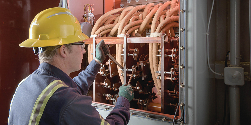
Prior to the site visit, some background information is necessary for an accurate proposal from the LTC-inspection provider. Information such as when the LTC was last serviced, what was done, and the results (Figure 1) of the most recent oil analysis (DGA and any filming or particle count data) should be reviewed and a recommendation provided.
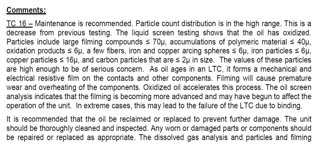
Figure 1: The mechanical nature of the LTC warrants regular physical inspections, in addition to oil and DGA testing. These inspections can be time-based or condition-based.
The oil from the main transformer tank and the oil from the LTC require different oil tests. Along with DGA, it is important to conduct moisture analysis as well as particle count and filming compound analysis of the LTC fluid.
Photos allow the tech team to identify the specific manufacturer and model of the LTC. Some LTCs can only be serviced by the original manufacturer. If the LTC can be serviced, photos help define the current condition of the tank and the tank’s surroundings so the technician can properly prepare for the site visit.
LTC servicing requires a planned outage. If the LTC is not on a double-ended substation, it is best to couple the service with other maintenance tasks that require a shutdown. LTC servicing generally requires a full day to complete. Depending on the severity of work needed, it can vary by a couple of days. Wear parts, such as contacts, typically can be obtained within a day for replacement. Some parts may require a return trip to replace.

Inspecting and Cleaning Contacts
Physical Inspection
The field service team should conduct a comprehensive inspection by using steps that follow the industry’s best practices for determining the health of the LTC.
Controls and Electrical Functionality
First, the technician verifies the functionality of the LTC controls and performs an electrical check before the oil is drained, especially on LTCs that have a charging spring. The technician ensures the position indicator is working properly, the limit switches are operational, and the LTC operates through the entire range of positions and stops on position.
This portion of the inspection also includes checking the counter functionality, looking for signs of overheating in the control cabinet, hand cranking the safety interlock, and ensuring the control cabinet heater that controls humidity is working properly.
Tank Draining and Cleaning
To look inside the tank of the LTC, the technician drains the oil. The results of the initial testing and conditions found during the site visit determine whether the existing oil needs to be processed or replaced.
Next, the compartment is flushed with transformer oil and wiped clean to remove carbon and clean the components, which allows the technician a better look at the LTC’s overall condition.
Examining Consumable Components
Next, the technician checks the condition of the arcing tips on the stationary contacts and erosion on the main moving contacts. An LTC doesn’t typically run through the entire range of positions during normal operation, which means some contacts may not be engaged very often, if at all. These components are cleaned with an abrasive pad to remove filming, coking, or carbon.
If adjustments and cleaning don’t repair the functionality or if there is excessive pitting, filming, or wear, these parts will be recommended for replacement. The condition of the contacts will be included in the final report.
Manual Cranking
As the inspection continues, the LTC is manually cranked. This identifies issues with binding and areas that aren’t in proper working order, such as loose pins and cable connections on the mechanism. This also allows the technician to verify the timing and ensure proper contact alignment.

Wiping Down Filming and Carbon Deposits
Detecting Leaks
Removing the oil enables the technician to inspect the barrier panel/board that separates the main transformer tank from the LTC tank. The pressure difference between the oil in the transformer tank and the drained LTC tank can make it easier to identify damage, weaknesses, or leakage.
Replacing the barrier panel is an extensive undertaking that requires a significant period of downtime. It includes draining the transformer tank and the LTC tank, disconnecting the LTC, replacing the panel, reconnecting the LTC to the transformer, and refilling both tanks, which usually involves vacuum filling. Understanding the barrier panel’s poor condition and actively replacing it during a scheduled downtime is not uncommon.
Replacing Gaskets and Oil
The gasket around the exterior door of the tank is usually replaced even if there is no sign of a leak. After the technician seals the door, the tank is filled with new oil and a sample of the oil is drawn to establish the new baseline for future tests. The only time a technician returns the original processed oil to the tank is if the oil has minimal carbon present. That final determination is made on site.
Testing
After the tank is refilled, the field technician performs a dielectric test of the fluid as well as electrical tests. The ASTM D1816 spherical disk test is too sensitive for this purpose. Instead, the ASTM D877 flat disk method is the most accurate for LTC oil and meets the IEEE C57.106 standard for testing. Electrical testing typically is done when intrusive repairs have been made and includes transformer turns ratio (TTR) and winding resistance tests.
Conclusion
Transformer performance depends upon optimal functioning from all parts of the system, including the LTC. Due to the LTC’s mechanical nature, regularly scheduled maintenance conducted by skilled field technicians is critical to avoiding unplanned outages. Along with oil testing and analysis, regular servicing of the LTC ensures corrective steps are taken before it becomes a legitimate threat to your operation.
 Robert T. Rasor is Director of Transformer Services at SDMyers, where he has been a member of the engineering team for 41 years. Robert has worked in several positions from a product design and field commissioning engineer to his current role directing field services, operations, and plant management. He is active in technical societies including IEEE. Bob is the SDMyers Technical Director.