
The status of the insulation in a rotating machine can be evaluated using various testing techniques. Static tests are performed while the motor is disconnected from the system, typically during manufacturing, commissioning, maintenance, or repairs. The goal of a static test is to provide an accurate picture of the machine’s electrical characteristics. Static tests can often be performed from the motor control center and thus do not require opening or disassembling the motor in any way.
TESTING INSULATION STATUS
This article reviews the theory behind each of the static tests used to evaluate the status of the insulation of rotating machines, including tests to evaluate the ground wall insulation system using high-voltage direct current (DC) tests: insulation resistance, polarization index, dielectric absorption ratio, step voltage, and dielectric voltage withstand (hipot).
We also explain how to use voltage surge tests to evaluate the status of the turn-to-turn insulation, which is the weakest spot and the place where most insulation failures originate in a motor. During surge tests, voltage pulses are injected into the machine windings to simulate the startup process where a nonlinear voltage distribution exists across the winding. The results can be used to diagnose the condition of the machine’s insulation system and can be used to plan machine replacement or overhaul when trended over time.
Best practices and applicable standards, as well as the criteria used to analyze the condition of the insulation in rotating machines, and test results of faults found using the different types of static tests, are presented.
Note: Additional types of static tests that apply high-voltage alternating current (AC) at nominal or very-low frequencies are not covered in this article.
Why Test
Electric motors use as much as 45% of all energy and are essential to all industries. Investing in preventative maintenance programs capable of detecting and correcting potential failures before they happen is essential for protecting operations.
A significant number of electric motor failures are related to the insulation system.
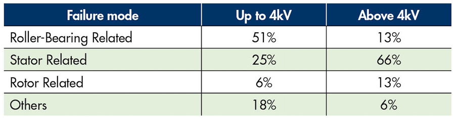
Table 1 summarizes the failure modes by incidence for two voltage levels. Most stator- and rotor-related failures start as — or are the consequence of — a failure of the insulation system on the machine.
When to Test
Tests should be performed when the motor is built or rewound or during any maintenance cycle. One of the purposes of maintenance tests, particularly insulation tests, is to evaluate the motor’s location in the reliability curve (Figure 1). When the motor is built, the winding-to-ground insulation breakdown voltage is very high. This is represented in the curve as the point where it touches the vertical axis. As the motor ages, the insulation is degraded, and the insulation breakdown voltage begins to drop. This process is initially very slow but accelerates over time as the motor insulation ages. The motor fails when the breakdown voltage is lower than the bus voltage.
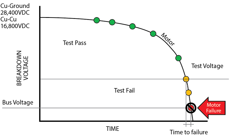
Figure 1 also shows why it is important to test at voltages higher than the nominal voltage of the motor. Once an insulation test fails, the motor will very soon fail if it is put back into service even if the breakdown voltage is still higher than the bus voltage of the motor.
Types of Tests
- Insulation tests fall under the category of static tests, which are performed with the motor disconnected from the main power. The most frequently used insulation tests are the basic DC insulation test (a.k.a Megger test), polarization index (PI), dielectric absorption ratio (DAR), step voltage, hipot, surge, partial discharge, and power factor tip-up tests.
- Other static tests involve measuring the parameters of the windings as well as contact resistance. Winding parameters such as winding resistance and inductance are measured as part of a routine procedure to look for changes in the windings such as shorted turns or improper winding. Contact resistance is also evaluated using low-resistance ohmmeters.
A typical test sequence consists of:
- Impedance measurements.
a. Winding resistance
b. Winding inductance - DC insulation tests
a. Basic insulation test
b. Polarization index (PI) or dielectric absorption ratio (DAR) tests
c. Step voltage test
d. HiPot test - Surge tests
TEST INTERPRETATION
In the following sections, we discuss how to perform and interpret this sequence of tests.
Impedance Measurement
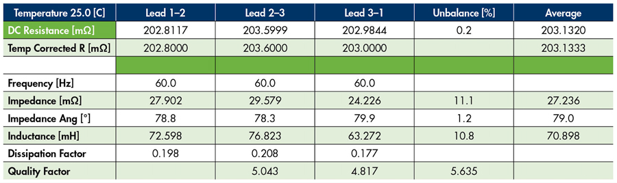
For this first test, winding resistance and inductance are measured and compared. Ideally, similar windings in the machine will have similar parameters, e.g., the windings for phases A, B, and C in an induction machine should have similar resistances and inductances. This can be used to find issues after the machine is initially built, after a repair, or during scheduled maintenance. Ideally, the measured resistances and inductances of the three phases will be equal or very close to each other in value as can be seen in Table 2.
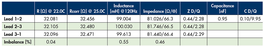
Differences in winding resistance can indicate missing or extra turns, wrong copper diameter, turn-to-turn shorts or opens, and problems with rusted, loose, or even broken connections. Differences in inductance can also indicate missing or extra turns or wrong connections of groups of turns.
Imbalance expressed as a percentage is the easiest indication of such differences. For a new motor, the % imbalance should be lower than 1%; for repaired motors, a percentage up to 3% is acceptable; and a difference of up to 10% can be considered acceptable for in-service motors. Trending these values over time is a valuable diagnostic tool.
Remember that inductance values are a function of the position of the rotor inside the machine and should therefore be approached with caution (Table 3). Only by comparing the values when the rotor is outside the machine can they be expected to be equal or very close to each other.
Basic Insulation Test
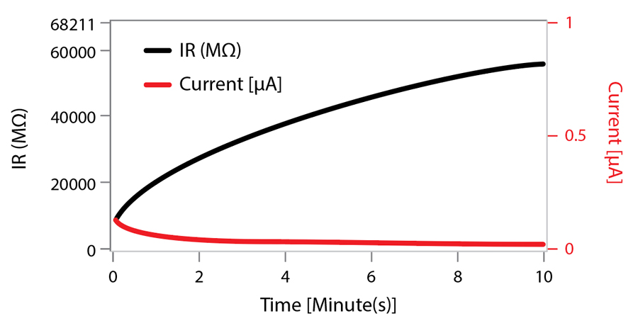
The basic DC insulation test is by far the most popular type of insulation test. It is performed to determine whether the motor´s insulation resistance is above a certain value. Insulation resistance is measured by applying a fixed DC voltage to the ground wall insulation of the motor, as shown in Figure 2. During the test, the circulating current is measured, and the resistance is calculated using Ohm´s law.
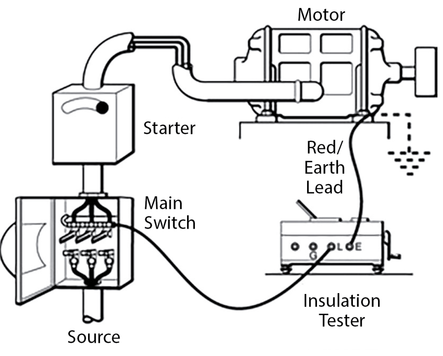
When injecting DC into a motor in the manner described in Figure 2, the insulation system behaves as a capacitor. This results in a transient electrical process that takes some time to settle as can be seen in Figure 3. During this process, several phenomena take place simultaneously: capacitive charging current, polarization of the insulation material, and absorption along with circulation of current due to leakage resistance. The insulation resistance test seeks to determine the leakage current that is due to the insulation resistance of the motor’s insulation system.
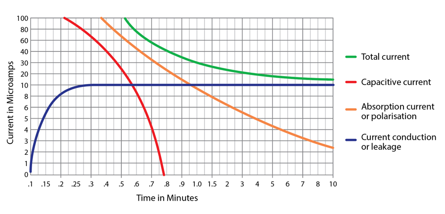
For this reason, insulation resistance values are not taken immediately after applying DC voltage; some time is allowed to pass before determining the insulation value to be used. To obtain consistent results, a time of 1 minute is usually used for reading the insulation resistance value.
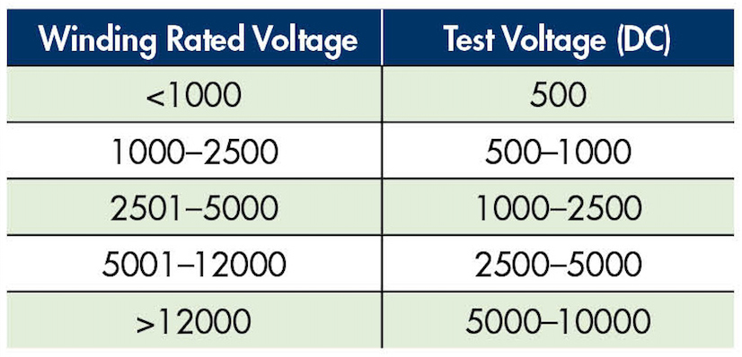
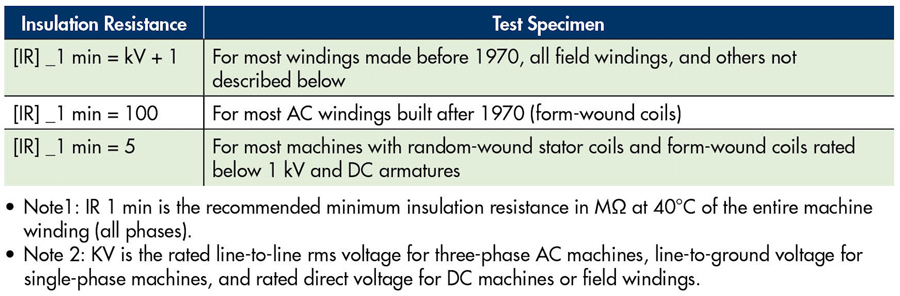
IEEE Std. 43, IEEE Recommended Practice for Testing Insulation Resistance of Electric Machinery[1] offers the following guidance for insulation resistance test voltages with respect to the rated line-to-line voltage for three-phase AC machines, line-to-ground voltage for single-phase machines, and rated direct voltage for DC machines or field windings. The recommended minimum insulation resistance value should be as specified in Table 4. This table also applies to PI and DAR tests.
Insulation resistance values are temperature dependent, e.g., a 400 MΩ value measured at 20°C means 200 MΩ at 30°C and 100 MOhm at 40°C. For this reason, insulation resistance values are temperature corrected to 40°C so they can be evaluated against the standard and compared to each other.
The temperature-compensated insulation resistance results are then compared to the minimum insulation resistance values established by the applicable standards. Table 5 from IEEE Std. 43 tells us the minimum temperature-compensated insulation resistance value for each type of motor.
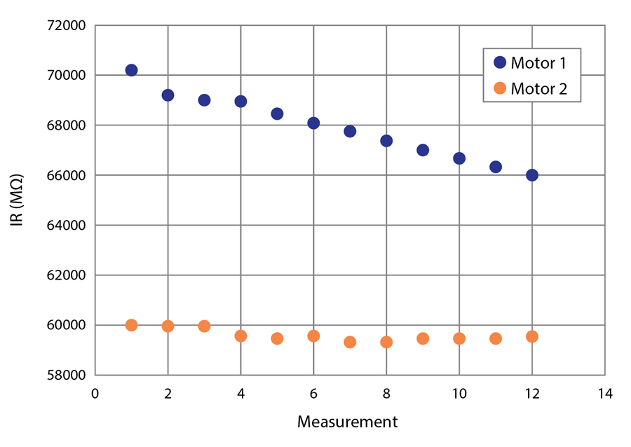
Historical temperature-compensated values of this test can be trended (Figure 4). A downward trend can indicate a problem developing with the insulation even when the absolute value of the insulation resistance is high. A stable trend even when the values are low can indicate an insulation system in good shape. Motor 2 is probably in good condition even though it has a lower absolute value of insulation than Motor 1. Motor 1, on the other hand, needs to be investigated because the insulation has been steadily decreasing.
The basic insulation test is a go-no-go test in which failure tells us that the motor’s insulation is in bad shape. However, a pass cannot guarantee that the insulation in the motor is good.
Polarization Index Test
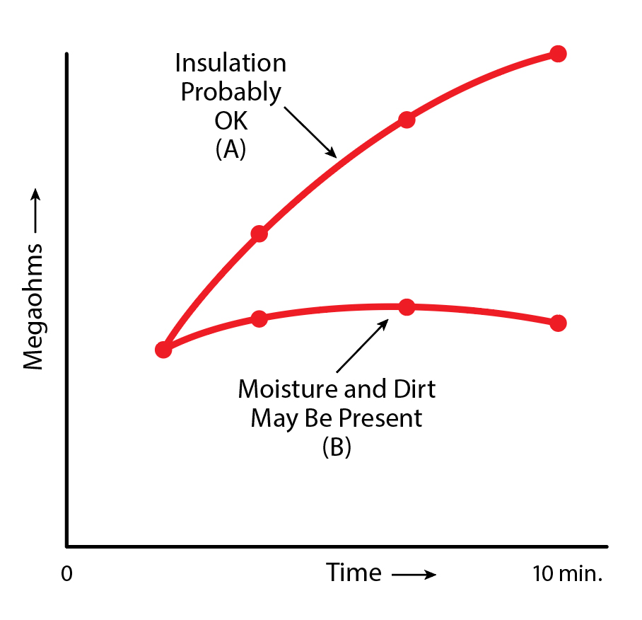
During the insulation resistance test, a process called polarization happens in the insulating material. This process involves all polar molecules inside the insulation system. It is expressed by current flowing into the insulation system that is high initially but drops as the molecules of the insulation align with the applied voltage. This means that a lower insulation resistance value is initially to be expected due to the higher current, but the insulation resistance value will recover over time (Figure 5).
Other polar molecules such as water and certain contaminants can cause this process to take longer than expected. This will reflect in the insulation resistance remaining at lower values and not recovering to the expected values (Figure 6).
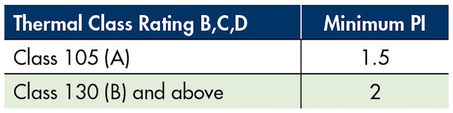
This recovery is characterized during the PI test by calculating the ratio of two resistances measured at separate times during the test. Typically, the resistance at 10 minutes is divided by the resistance measured at 1 minute: 𝑅_10/𝑅_1. Some instruments will calculate the PI value using total current as can be seen in 𝐼_1/𝐼_10. As a rule, the higher the PI value, the better the status of the insulation.
Table 6 from IEEE Std. 43 shows typical PI values for several types of insulation material and motor classes.
The PI test is not applicable to non-insulated field windings. However, newer insulation types that recover extremely quickly have placed into question the value of the PI test for these kinds of insulation. The dielectric absorption ratio (DAR) test uses the same principle as the PI test, but the ratio is calculated between the resistance at 1 minute and the resistance at 30 seconds — or the inverse if currents are used. Although higher values of DAR are recognized as better, no standard recognized values exist for this test.
Polarization index and dielectric absorption ratio tests are performed at the same voltage as the basic insulation test shown in Table 4 and are typically performed as an extension.
Step Voltage Test
In an ideal insulation system, insulation resistance should remain constant as voltage increases. A healthy insulation system will follow similar behavior within the boundaries of its own maximum breakdown voltage. This characteristic is used during a step voltage test in which the voltage is increased in fixed steps starting at the basic insulation test level and going up to a maximum value established for the motor’s voltage class.
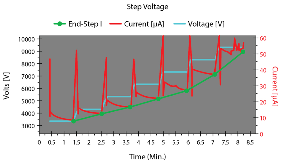
Five voltage steps are typically used. The voltage for each step is kept constant during a 1-minute interval. At the end of each interval, leakage current is measured and the insulation resistance is calculated. As voltage increases, the current is expected to increase in the same proportion, according to Ohm’s law, but resistance should remain stable. During the test, a voltage vs. leakage current graph is drawn. A line is then drawn connecting the leakage current values at the end of each interval (Figure 7).
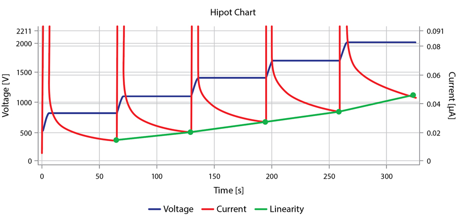
A straight line indicates a healthy insulation system since it means that the resistance value is constant during the test, i.e., the resistance is independent of the applied voltage. A curved line, like the one shown in Figure 8, indicates that resistance changed — usually dropped — at some point during the test, which will be signaled by a higher-than-expected increase in the leakage current. This voltage dependence on the insulation can be an indication of early partial discharge occurring inside the motor.
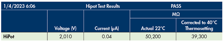
High Potential Test
The high potential or hipot test is performed to verify that the insulation system can withstand the voltage applied. DC or AC voltage is applied for 1 minute; the voltage magnitudes to be used are defined in IEEE Std. 95-2002, IEEE Recommended Practice for Insulation Testing of AC Electric Machinery (2,300 V and Above) With High Direct Voltage.[2]
Surge Test
During the motor’s life, certain transient processes such as starts, stops, and transients resulting from switching electronic valves in VFD-fed motors are present. This results in a nonlinear distribution of voltage across the motor windings (Figure 9).
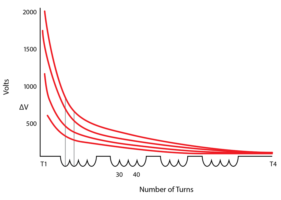
This nonlinear distribution of voltage means that the initial turns are the section of the winding that suffers the fastest degradation in the entire insulation system. This is expressed by a lower value of turn-to-turn insulation resistance in these first few turns in each motor winding, which eventually results in a few shorted turns inside the windings. Shorted turns result in a so-called transformer effect where these turns behave like a shorted secondary winding in a transformer. Even a small, induced voltage produces circulation of a high current, which then burns through the motor’s insulation via the joule effect. Remember that the power dissipated in resistance is directly proportional to the square of the current: P = Iˆ2 * R.
Turn-to-turn insulation failure is the main cause of insulation failure in electrical motors; as much as 80% of stator failures start as turn-to-turn faults.
The surge test is designed to simulate the nonlinear distribution of voltage in the motor’s winding. The equivalent circuit for a surge test is presented in Figure 10.
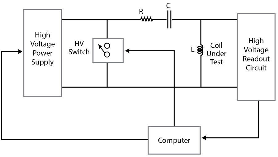
The capacitor is charged at the initial test voltage, and the energy stored in the capacitor is discharged into the motor’s winding. Several pulses are applied at the same test voltage. Voltage is then increased, and the process is repeated until a maximum test voltage has been reached, a turn-to-turn failure has been found, or a breakdown condition has been detected.
Figure 10 shows that a series RLC circuit is formed during the test by the motor’s winding and the ringing capacitor. The resulting oscillating voltage measured at the capacitor has a waveform like the one in Figure 11.
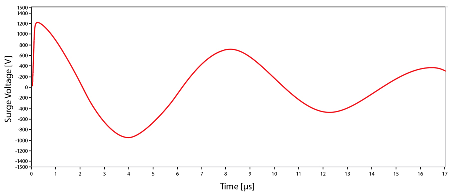
The frequency of this voltage is constant and depends only on the electrical parameters of the circuit as can be seen in this equation:
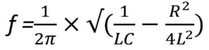
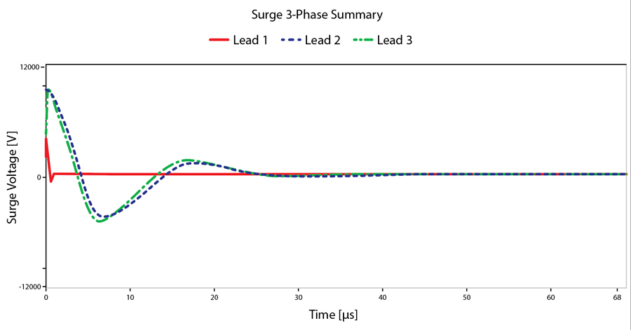
A change in frequency is an indication of a change in the electrical characteristics of the RLC circuit formed by the ringing capacitor and the motor winding under test. The capacitance value is kept constant during the test and, barring equipment failure, depends exclusively on the design of the test equipment used. Therefore, any change in frequency indicates a change in the electrical characteristics of the winding under test. When a short happens between turns in the winding, the inductance of the winding changes with the square of the number of turns. This reflects as a sudden change in the frequency of measured voltage as can be seen in Figure 12, which presents actual measurements of tests performed on a 4,160 V motor. The resulting waveform for Lead #1 is completely different from the other two.
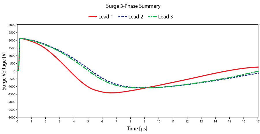
As we can see in Figure 13, the area under the curve is significantly different for two consecutive pulses if the frequency between them changes. This characteristic is used to detect turn-to-turn insulation failure during surge tests. A parameter known as pulse-to-pulse error area ratio (EAR) is calculated as the ratio of the normalized area under the curve for two consecutive pulses. If that value, expressed as a percentage, exceeds a certain predefined setting, an insulation failure is declared.
It is important to note that when a turn-to-turn short is present from the beginning of a test for a particular winding, there is the possibility of finishing the test all the way to the maximum voltage without experiencing a change in inductance. Therefore, we would be led to think that everything is OK with the winding.
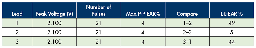
In this case, comparing the error area ratio results between motor windings can be useful, since all the windings should have similar inductances and therefore present similar behavior. This line-to-line error area ratio (L-L-EAR%) comparison is especially useful in induction machines when the rotor is outside the stator since the position of the rotor inside the stator can influence inductance values and therefore the results of the test.
Test Voltage
Two common questions are often asked when performing insulation tests:
- How much voltage should I apply to the motor for this test?
- Will testing at voltages higher than nominal line voltage damage the motor?
To answer the first question, let’s remember that:
a. When the motor is built, the insulation breakdown voltage is much higher than the nominal voltage of the motor.
b. During the motor’s life, it sustains voltage transients with magnitudes up to 5 times the peak line to neutral voltage (pu): p.u. = √(2/3) xV _line.
c. In Figure 1, we saw that as the motor approaches its end of life, degradation of the breakdown voltage happens very quickly.
Tests such as step voltage test, hipot, and surge should be performed at voltages higher than the nominal voltage of the motor. Different standards have different recommended test voltages, and proper discussion of all of them goes beyond the scope of this article. A compilation of recommended test voltages for different standards can be found in “The State of Surge Testing on Induction Motors.”[5] A useful and practical rule of thumb used in the industry is to test at a voltage equal to twice the nominal voltage plus 1,000 V:
V = 2x Vline+1000 V. This aids in selecting the proper test instrument for a specific case.
GENERAL NOTES
The insulation tests mentioned here can usually be performed at either the motor or the MCC. When performing these tests at the MCC, the tester should be aware that the results include cables, breakers, other equipment, and the motor. If an insulation issue is found, it is then necessary to disconnect the motor from the MCC and test again. On the other hand, the capacitance of cables and auxiliary equipment must be considered when selecting the test equipment. It will sometimes be necessary to disconnect the motor from the cables and test at the motor rather than the MCC if the test equipment does not have the required energy output for the test.
SUMMARY
Regularly testing motors can help prevent outages and avoid future pitfalls by recognizing patterns in the test results. Motor testing should be included in a complete program that includes low-voltage and high-voltage testing to diagnose and trend specific parameters related to the equipment’s electrical health.
This article presented a sequence of tests usually performed on motors during the initial stages of the motor’s life and during regular maintenance checks. This simple, tried-and-true sequence of tests helps identify issues with motor insulation and can prevent costly downtime.
REFERENCES
[1] IEEE. IEEE Std. 43-2013, IEEE Recommended Practice for Testing Insulation Resistance of Electric Machinery, 2013. [2] IEEE. IEEE Std. 95-2002, IEEE Recommended Practice for Insulation Testing of AC Electric Machinery (2,300 V and Above) With High Direct Voltage, Power Engineering Society, 2002. [3] Megger. A Stitch in Time: The Complete Guide to Electrical Insulation Testing, 2006. [4] EASA. EASA Technical Manual, Section 7 Electrical Testing, January 2019. Accessible for members at https://easa.com/resources/easa-technical-manual. [5] SKF Group. “The State of Surge Testing on Induction Motors,” 2013. Accessed at: http://www.cmcbaker.com/manuals/surge%20test%20whitepaper.pdf.
Abel Gonzalez has been a Senior Relay Applications Engineer with Megger LTD in Markham, Ontario, since 2013. His research areas include analysis operation, control, and protection of electric power systems. Following several appointments in the Faculty of Electrical Engineering at the Universidad Central de Las Villas, Cuba, where he taught courses in electrical drives and power electronics, and worked as a Tele-Traffic Engineer, Control Engineer, and Head of the Marketing Department for the Cuban Telecommunications Company as well as a professor of Marketing and Electrical Engineering, for the Universidad Central de Las Villas, Cuba, Abel worked as a Design Engineer for Arteche Medición y Tecnología in Zapopan, Jalisco, Mexico, and Curitiba, Brazil. He earned BS and MSc degrees in electrical engineering from the Universidad Central de Las Villas, Cuba.

Swapnil Marathe has been a Substation Application Engineer with Megger since 2020. His focus is testing transformers, batteries, and motors. He previously worked as a Megger intern on relay and Substation applications. Swapnil graduated from the University of Texas at Arlington with a BS in electrical engineering.