
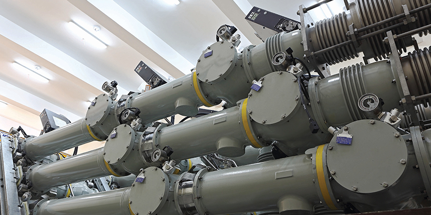
In gas-insulated substations (GIS), the high-voltage elements, including conductors, circuit breaker interrupters, switches, current transformers (CTs), and voltage transformers, are encapsulated in SF6 gas inside grounded metal enclosures.[1] For that reason, direct access to circuit breaker (CB) main circuit terminals for testing purposes is not possible.
The inaccessibility of main circuit terminals requires several actions to be taken before conducting the measurements. One of these actions requires disconnecting the ground connection (detachable shunt that connects the main circuit to the grounded enclosure during testing) from one side of the breaker. This action reduces the safety of the test procedure.
According to regulations and demands described in IEEE Std. 510-1983[2] and Ostojic and Milovic,[3] all conducting points in the substation must be grounded during testing and maintenance. In the previously published paper by Ostojic and Secic[4] on this topic, we presented a novel method for testing high-voltage (HV) circuit breakers in GIS substations without the need to remove the ground connection. This new method is based on injecting high DC current through the parallel connection of the grounding path and main circuit, as well as measuring the response signals on the CT’s secondary.
This method, however, is not applicable for GIS configurations where the CT is not included in the measurement circuit between the maintenance grounding switches. It is also not applicable for single-pole controlled GIS circuit breakers (with three separated enclosures) with very-low grounding path and enclosure resistance (≤ 50–60 µΩ). Consequently, we propose an improved GIS test method based on the test procedure previously described in Ostojic and Secic.[4]
GENERAL PROBLEM IDENTIFICATION
To measure operating times [opening time (O), closing time (C), open-close time (O-C), close-open time (C-O), etc.] on the CB main circuit in the GIS substation with the conventional testing method, the CB main contact terminals must be accessed through the maintenance switches (Figure 1). By removing or disconnecting the detachable shunt, one side of the breaker is disconnected from the ground, which enables measurements without removing SF6 gas or opening the enclosure. However, the procedure to remove this shunt is unsafe, time-consuming, often impractical, and as such, is undesirable for test personnel in the utilities.[4] Furthermore, some GIS circuit breakers do not have purpose-built detachable shunts and test terminals that are isolated from the GIS enclosure.[5]
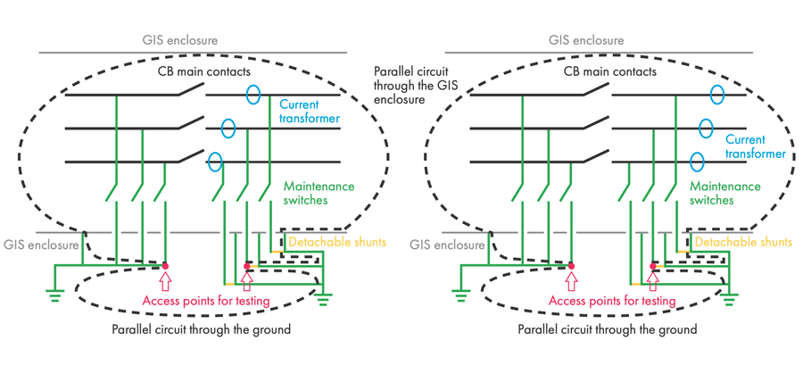
Figure 1: Electric Diagram of GIS CB, CTs Within (a) and Outside (b) Earthing Switches Circuit
If the detachable shunt is not removed or disconnected, a parallel conducting circuit to the one consisting of the tested main circuit path is formed. The resistance of this parallel circuit consists of the resistance of the GIS enclosure and the grounding itself, and it is often comparable to or even lower than the resistance of the main circuit.
To experimentally verify this claim, a high-precision micrometer with a test current of 500 A was used to measure GIS enclosure resistance on several GIS substations. The lowest measured value reached was 20 µΩ.
This prevents a conventional CB timing measuring system from being able to deliver reliable results.
EXISTING METHOD SHORTCOMINGS
The test method proposed in Ostojic and Secic[4] is based on the injection of the high DC current in parallel through the main circuit and GIS enclosure of all three poles and the simultaneous measurement of the response signals on the secondary of the CT during the circuit breaker operation. One power source must be connected between two marked access points for testing (Figure 1) where the main circuit is accessed through the maintenance grounding switches. This power source is a voltage-controlled DC current source with a high current output (up to 500 A), based on state-of-the-art power electronics converters.
Current transformers are an essential part of the HV GIS substation. One (primary) terminal of these elements is located in the pressurized gas area, while the secondary terminal is accessible in the auxiliary circuits.[6]-[8] These accessible CT secondary terminals can be used for measuring operation time in HV GIS circuit breakers. The measuring instrument should record either voltage or current on the CT secondary; based on this, the instant of the CB contacts touch or separation can be detected.
This method is successfully applied to GIS circuit breakers where the CT is available between test access points (grounding switch terminals) as shown in Figure 1a, even if the GIS switchgear does not have detachable shunts and test terminals. Another approach to this problem, described in Renaudin and Nenning,[9] is based on the usage of a Rogowski coil to measure the current variation in the ground conductor or the breaker path over time.
However, the test method described in Renaudin and Nenning[9] is not applicable in the case when the tested circuit breaker does not include the detachable shunts since there is a permanent parallel connection across the enclosure to the main circuit. The Rogowski coil, essential for the current variation measurement for this test method, cannot be installed on such a circuit breaker.
For the method described in Ostojic and Secic,[4] the first limitation is related to the GIS configurations where the current transformer cannot be included in the measurement circuit (as shown in Figure 1b). In this case, there are no response signals on the secondary of CT, based on which a change in the main contact state is detected.
Another challenge for Ostojic and Secic[4] is related to some single-pole operated GIS circuit breakers (each pole has its enclosure) with very-low resistances of the pole’s enclosures (lower than 50–60 µΩ). Our experimental results showed that a total current of 500 A, when divided into three current paths (poles), is not always enough to get a measurable response signal at the secondary of CT. For example, if the resistance of the GIS enclosure and the grounding path is about 30 µΩ and the resistance of the main arcing contact is about 1 mΩ, only about 5 A of the total 166 A (one-third of 500 A) will initially flow through the main circuit.
For CTs with high transmission ratios, e.g. 4,000:5, the value of the secondary current will be around 5–6 mA, which can be highly affected by external or measurement noise. This again can make the circuit breaker timing measurement results unreliable. The solution to this problem is to increase the test current by at least twice the value of the required test current per pole, which is about 330 A, or about 1,000 A in total.
IMPROVED TEST METHOD
The improved test method presented is applicable to the most demanding cases for testing, such as a single-pole operated GIS CB that has very-low resistance in its pole enclosures or where CTs cannot be included in the measurement circuit between test access points.
The first improvement to the GIS test method[4] consists of replacing the high-frequency DC/DC converter as a power source with high-power lithium-polymer (Li-Po) batteries. The reason for this is to eliminate converter noise. As shown in Figure 2, three isolated battery-based power sources are used to supply each pole of the single-pole controlled CB with a high current. Therefore, three such power sources integrated into one box will be needed for testing this GIS configuration. The current will be in the range of 400–500 A per pole, depending on the battery charge levels and the resistance of the tested circuit.
Figure 2: Three Battery-Based Power Sources Used for GIS CB Testing
The second improvement is related to the measurements on GIS breakers with the CT placed outside of the grounding switch circuit. In this case, instead of measuring the signal at the secondary of the CT, the primary current can be monitored within the power source. Since each pole of the GIS circuit breaker is supplied with a very-high DC current (400–500 A), the change in the main contact state will cause a change in the total current that is measurable even in the case of the very-low resistance of GIS enclosures and grounding path. For easier detection of the signal transients, it is possible to measure the current signal through the measurement shunt or the time derivative of this signal. This measurement can be realized with a hardware differentiator based on operational amplifiers.[10]
METHOD VERIFICATION
Verification of the improved test method for GIS CB testing was performed on the GIS circuit breaker model Energoinvest SFI 11 (manufactured in 1985), single-pole operated, without purpose-built test terminals. Since there were no purpose-built test terminals (access points), test clamps of the current cables were connected to the conducting points at the GIS enclosure, placed as close as possible to the earthing switches, as can be seen in Figure 3.
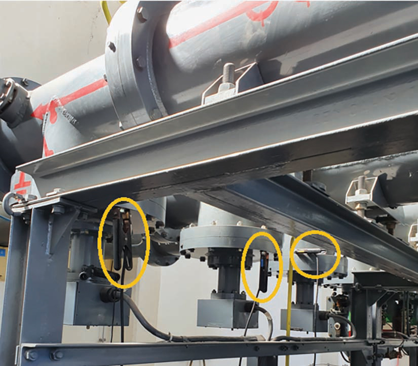
Figure 3a: Connection of Current Clamps to Points Close to Earthing Switches
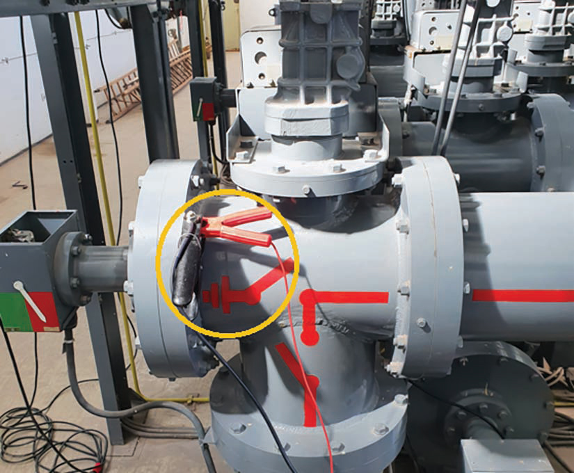
Figure 3b: Connection of Current Clamps to Points Close to Earthing Switches
Since CTs were included in the test circuit, response signals were measured at the CT secondary. Besides the fact that the circuit breaker was single-pole operated (with three separate enclosures) and didn’t have purpose-built test terminals, one more aggravating circumstance was the very-low resistance of the grounding path (around 60 µΩ).
The generated test current was in the range of 420–430 A per current output. The measured current signal at the secondary of the CT during opening and closing operations is shown in Figure 4. As concluded in Ostojic and Secic,[4] the highest or the lowest (depending on the signal direction) turning point at the response signal during the opening operation matches with the instant of the arcing contact separation, while the instant of the first appearance of the current signal during the closing operation matches with the instant of the first contact touch.
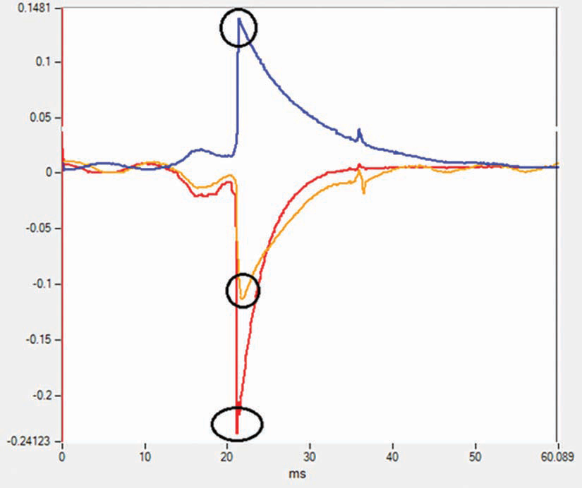
Figure 4: Signal Response at CT Secondary During a) Opening
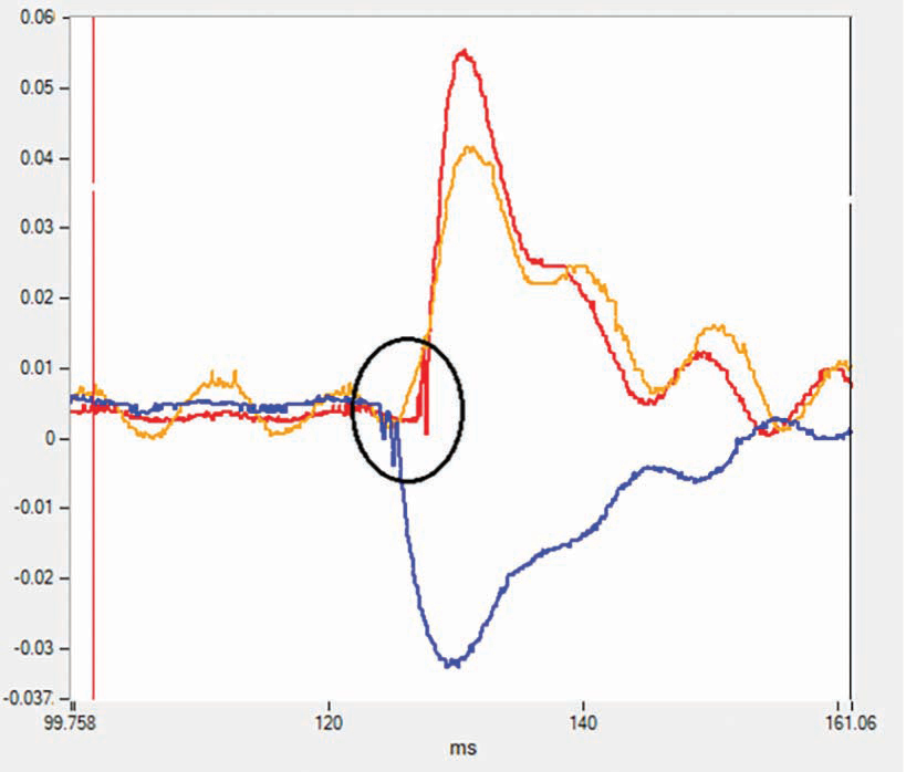
Figure 4: Signal Response at CT Secondary During b) Closing Operation
With this in mind, and looking at Figure 4, it can be seen that instants of the contacts opening are around 21–22 ms, while the instants of the contacts closing are in a range of 125–128 ms. These instances can easily be detected automatically with the appropriate software.
The results could not be verified by performing timing measurement with the conventional timing method since it is not applicable for this case without dismantling the GIS enclosure (a GIS circuit breaker doesn’t have detachable shunts). Instead, specified limit values prescribed by the OEM were considered. According to these specifications, circuit breaker model Energoinvest SFI 11 has an opening time in the range of 18–24 ms and a closing time in the range 120–130 ms, meaning that interpreted values are within the allowed range.
CONCLUSION
Method verification has shown that this improved test method with three isolated high-power current sources (400–500 A per source) is applicable for single-pole operated circuit-breakers without test terminals and with very-low resistance of the grounding path.
Because of the option of direct measurement of the injected current changes as an alternative to measurement of current signal response at the (CT’s) secondary, this can be applied to all configurations of GIS switchgear: three-pole or single-pole controlled circuit breaker with or without CT in the measurement circuit and with or without test terminals.
REFERENCES
[1] Electric Power Substations Engineering. Electrical Engineering Handbook, Edited by John D. McDonald, CRC Press Published May 16, 2012. Reference – 536 Pages – 271 B/W Illustrations ISBN 9781439856383 – CAT# K12650.
[2] IEEE. IEEE Std. 510-1983, Recommended Practices for Safety in High-Voltage and High-Power Testing.
[3] Radenko Ostojic, Budo Milovic. “New Requiremens in Circuit Breaker Diagnostics: Integration of New Circuit Breaker Test Methods,“ NETA World, 2014.
[4] Radenko Ostojic, Adnan Secic. “Improving Safety in Operation Time Measurement Procedure for Circuit Breakers in Gas Insulated Substation,” Research Disclosure, 2019.
[5] Philip Bolin. Mitsubishi Electric Power Gas-Insulated Substation, 2003 by CRC Press LLC.
[6] IEEE. IEEE Std. C37.122.1-1993, Guide for Gas-Insulated Substations.
[7] IEEE. IEEE Std. C37.123-1996, Guide to Specifications for Gas-Insulated, Electric Power Substation Equipment.
[8] IEC. IEC 62271-203:1990, Gas-Insulated Metal-Enclosed Switchgear for Rated Voltages of 72.5 kV and Above (3rd edition).
[9] T. Renaudin, A. Nenning. OMICRON electronics. “On-Site Non-Intrusive Testing of AC Circui Breakers,” CIGRÉ Winnipeg 2017 Colloquium, Study Committees A3, B4, & D1, Winnipeg, Canada, September 30–October 6, 2017.
[10] Radenko Ostojic, Adnan Secic. “Combined Current and Voltage Controlled Source in Arcing Contacts Condition Assessment,“ NETA World, 2015.
 Radenko Ostojic is a Test and Diagnosis Engineer at DV Power – Sweden in the field of circuit breaker testing and maintenance. He has been employed at DV Power since 2010 and works on improving circuit breaker testing equipment and developing new methods for circuit breaker testing. Radenko’s area of special interest is testing circuit breakers in enhanced safety conditions, which implies testing of circuit breakers with both terminals grounded. He earned his BSEE at the University of East Sarajevo.
 Adnan Secic is an R&D Engineer at DV Power – Sweden. As a project leader, he is responsible for developing the circuit breaker analyzer and timer (CAT) device series. Adnan received his BS in electrical engineering and MS from the University of Sarajevo, and is in the final stage of Ph.D. studies at the Faculty of Electrical Engineering and Computing in Zagreb, Croatia.

Budo Milovic has been employed at DV Power since 2007 and currently works as a Technical Application Engineer for CAT instruments and circuit breaker testing. His area of interest is improvement of the circuit breaker testing equipment. Budo received his BSEE from the University of East Sarajevo, Bosnia and Herzegovina.

Kerim Obarcanin is a Manager of the Software Engineering Department at DV Power – Sweden and an Industry Expert Lecturer at the Sarajevo School of Science and Technology, a collaboration partner of Buckingham University, UK. His primary research focus is on the domain of data acquisition, conditioning, and algorithms for data processing. Kerim is currently in the final stage of his Ph.D. studies at the Faculty of Electrical Engineering in Sarajevo, Bosnia and Herzegovina.