

Multi-function protection relays calculate and use symmetrical components to enhance their performance during system faults. This can be illustrated in two specific examples: (1) zero-sequence current elimination for transformer differential protection and (2) negative-sequence current detection to inhibit out-of-step blocking.
Zigzag Transformer Inside Transformer Differential Zone
A shunt-connected zigzag transformer provides a zero-sequence current sink for ungrounded systems such as the one shown in Figure 1 by establishing a connection from ground to neutral. During a ground fault, zero-sequence current (I0) flows up through the neutral of the zigzag transformer. Therefore, it is simple to apply non-directional overcurrent protection for the detection of single line-to-ground faults. If the system is left ungrounded, high voltage appears on the unfaulted phases during single line-to-ground faults. This renders conventional ground overcurrent protection useless.
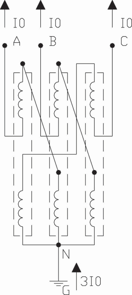
Figure 1: Zigzag Transformer Three Line Diagram
A zigzag transformer consists of three 1:1 ratio transformers. Each leg of the zigzag transformer consists of two windings that are 120 degrees out of phase. Windings are wound around the core such that zero-sequence current flows through the bank when there is system unbalance (i.e., ground fault). Only exciting current flows through a zigzag transformer during balanced system conditions. The grounding transformer appears as the leakage reactance of the core when a ground fault occurs and zero-sequence current flows evenly across the three phases.
A grounding resistor is sometimes used since the transformer alone equates to reactance grounding. Typically, the zigzag transformer is sized such that its impedance is 100 percent on its own base. The 10-second rating commonly applied throughout the United States is 400 amps primary.
If the zigzag transformer is located inside the transformer differential protection zone, such as for the delta connected windings shown in Figure 2, the zero-sequence current contribution during external ground faults must be eliminated. Otherwise, a misoperation can occur.
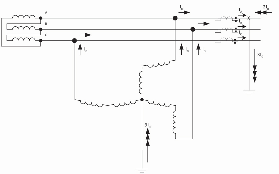
Figure 2: Ungrounded System with Zigzag Transformer for Ground Current
Numerical transformer protection relays can reliably remove the ground current using this method:
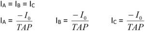
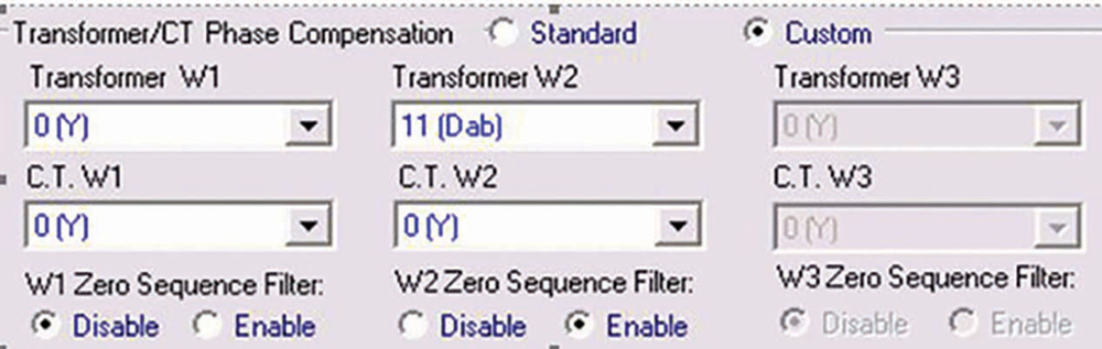
Figure 3: Zero-Sequence Current Elimination
The currents shown here are taken directly from the CT secondary and have been divided by the tap setting for the delta winding to convert them into per-unit. If zero-sequence current elimination is selected (see Figure 3 as an example), the relay calculates the ground current as follows:
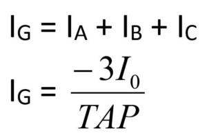
IA´, IB´ and IC´ are the internally compensated currents:
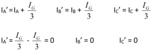
Figure 4 shows the transformer differential operating characteristic. Point A is the filtered operating point for an external ground fault; Point B is unfiltered.
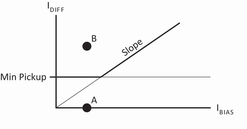
Figure 4: Transformer Differential Operating Characteristic
Negative-Sequence Current Detection to Inhibit Protection
Certain protection functions are typically intended to operate only during balanced three-phase conditions:
- Rate-of-change of frequency (81R)
- Loss-of-field (40)
- Out-of-step tripping|blocking (78)
- Under-voltage load shedding
If negative-sequence current (I2) is detected, it indicates an unbalanced disturbance is in progress. Figure 5 shows the oscillographic record captured by a relay for the simulation of a large generator that slipped three poles; the event evolved into a resistive ground fault.
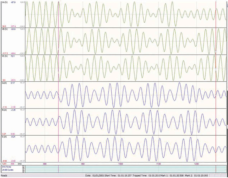
Figure 5: Pole Slip Evolves into Single Line-to-Ground Fault
Figure 6 shows two large generating units that are interconnected one substation away via the transmission system. If either machine becomes unstable, the desired sequence of events is to trip only the runaway generator while blocking the distance relays protecting the local transmission line terminals. This criterion prevents cascading outages and preserves the integrity of offsite power sources to the plant. For this particular case, the desired end result is to unblock the distance protection so as to clear the ground fault (Figure 6).
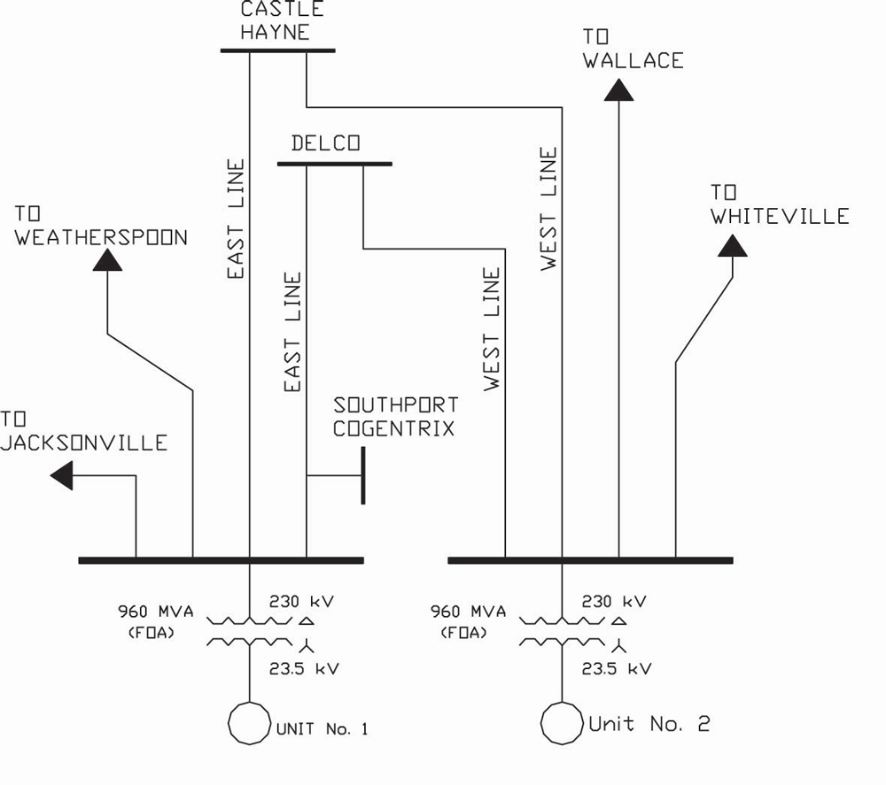
Figure 6: Two Large Generating Units Interconnected via the Transmission Grid
Figure 7 shows the trajectory of an unstable swing that passes through both the generator out-of-step (OST) tripping characteristic and a transmission line relay Zone 1 operating characteristic. Note that Point O corresponds to the generator voltage transformer terminals. Such a swing could operate both the line protection and the generator out-of-step tripping function; this illustrates why power swing blocking is required for transmission line protection. Phase distance protection can also operate during a stable swing, as shown in Figure 7.
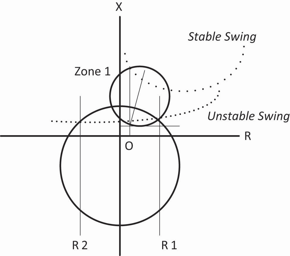
Figure 7: Unstable Swing Passes through Zone 1 and OST
Figure 8 is a simple logic diagram illustrating how to use negative-sequence current detection (46) to unblock the distance protection (21) after it has been inhibited by power swing blocking logic (78_PSB).
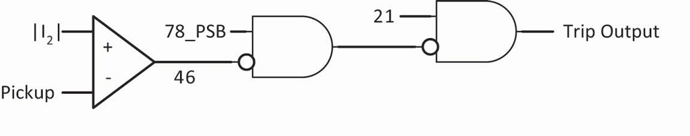
Figure 8: Negative-Sequence Current Unblocking
Another post swing disturbance that is even harder to detect is a three-phase fault on one of the transmission lines terminated at the plant following the first pole slip since no negative-sequence current is present. Figure 9a shows a typical power swing blocking (PSB) characteristic. If the impedance trajectory passes relatively slowly (e.g., three cycles or more) through the outer characteristic to the inner characteristic, then a power swing is detected and the phase distance protection is blocked. If there is a fault, the measured impedance will quickly (e.g., two cycles or less) jump from the pre-fault location to a point on the faulted power system.
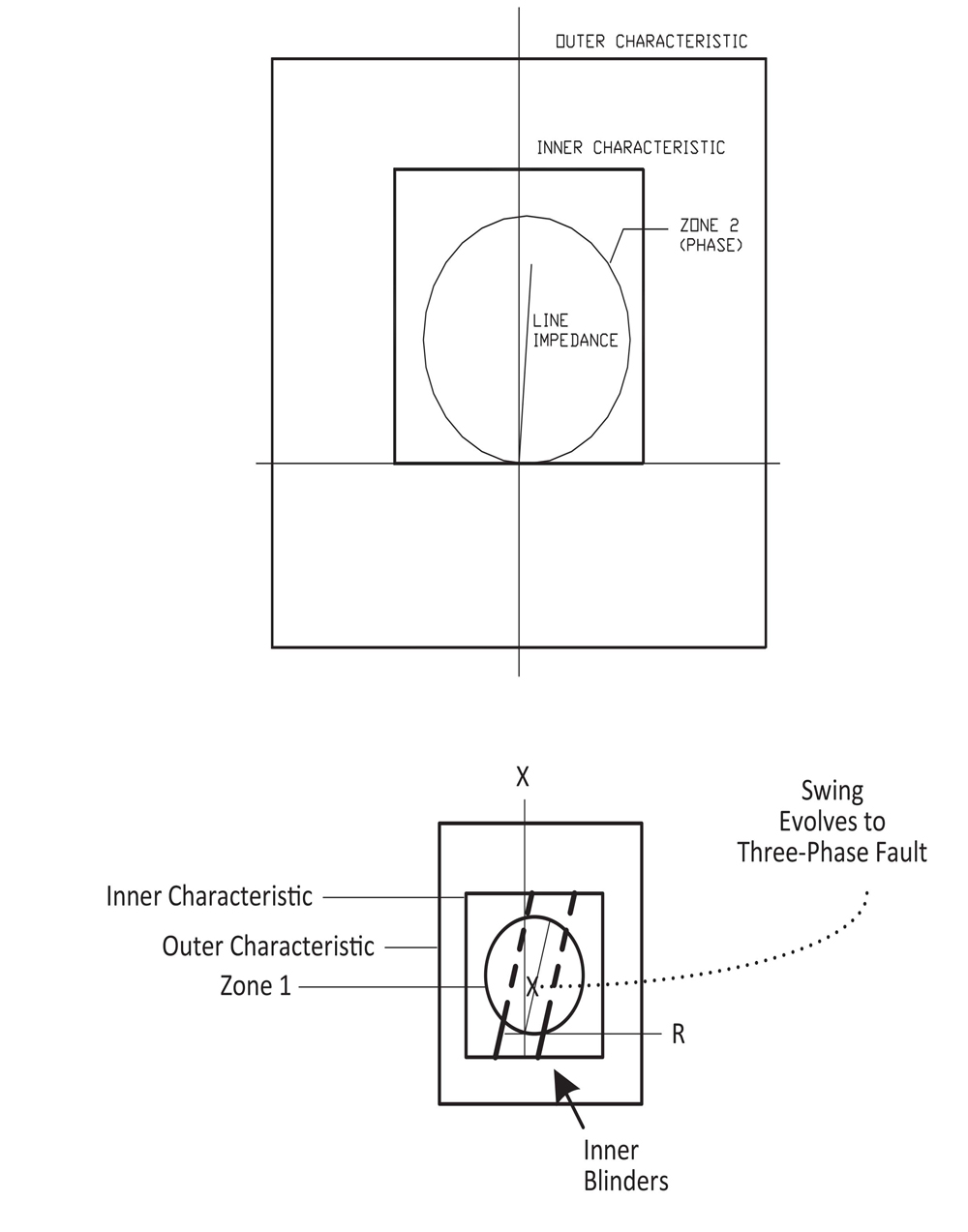
Figure 9a: Power Swing Blocking Characteristic
Figure 9b: Power Swing Blocking Inner Blinders
A pair of inner blinders is required to detect when a swing evolves into a three-phase fault as shown in Figure 9b. If a balanced line fault occurs, the measured impedance drops between the blinders and remains there; thus, the blinders can detect this condition and quickly unblock the phase distance protection.
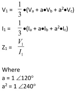
Out-of-step tripping|blocking characteristics operate on the measured positive-sequence impedance since a power swing is a balanced three-phase phenomenon. The positive-sequence impedance is calculated as follows:
Conclusion
Multi-function protection relays calculate and use symmetrical components to enhance performance during system faults. Using symmetrical component quantities helps provide more reliable and more secure protection.
 Steve Turner is a Senior Engineer II at Electrical Consultants, Inc., working in their San Diego office. Steve worked at Beckwith Electric Company, Inc. for 10 years, first as the Engineering Laboratory Director and then as Senior Applications Engineer. His previous experience includes working as an Application Engineer with GEC Alstom and as an Application Engineer in the international market for SEL focusing on transmission line protection applications. While at Duke Energy (formerly Progress Energy), Steve developed the first patent for double-ended fault location on overhead high-voltage transmission lines and was in charge of all maintenance standards in the transmission department for protective relaying. Steve has a BSEE and MSEE from Virginia Tech University.