
Electrical arc phenomena have been studied for a long time. It is an inevitable process that occurs during interruption of high electrical currents (e.g., during a short circuit current interruption). The effects of the electrical arc on the circuit breaker contacts are known, and great attention has been paid to developing methods to analyze arc behavior and minimize damage to the breaker contacts.
One mitigating solution is the separation of main and arcing contacts. Arcing contacts are responsible for carrying the arc inside the breaker chamber during the breaker operation, and those contacts must be designed to withstand high currents and high temperatures with minimal deformation and erosion. The real challenge is to learn about the state of these contacts during regular maintenance procedures. The goal is to reduce time spent on testing to bring down maintenance costs and keep equipment out of operation as briefly as possible. The arcing contacts are active (carrying current) only a few milliseconds. Thus, the test and the collection of useful data set must be adjusted to this very limited time frame.
Dynamic resistance measurement (DRM), already adopted and approved as the standard testing procedure by many maintenance companies, is usually based on recording a resistance and a motion curve during the opening operation of the high-voltage circuit breaker. However, by recording a dynamic resistance curve during the closing operation of the breaker, the useful data set can be extended; consequently, the diagnostic process is more reliable. The circuit breaker arcing contact is the first to make contact during a closing operation and the last to break contact during the opening. Therefore, arcing contact wear occurs during normal operation as well as when interrupting fault currents. If the arcing contacts are damaged, the breaker becomes unreliable very quickly.
An important diagnostic parameter is the main circuit resistance of the circuit breaker. This parameter is measured while breaker main contacts are in a closed position. For that reason, measurements can be recorded just before or after the DRM procedure, which reduces testing time since both measurements can be performed in one test sequence.
Safe and Fast Testing of Circuit Breakers with Both Sides Grounded
Safety in high-voltage substations is the highest priority for all personnel involved. Recent regulations and laws require all objects to be grounded on both sides before any maintenance work is performed. Eliminating the risk of induced high voltages improves the safety of test personnel and the instrument itself. This leads to a requirement for the modern circuit breaker analyzer to detect a main arcing contact’s state and to measure the operation time of the contacts when both circuit breaker terminals are grounded (Figure 1).
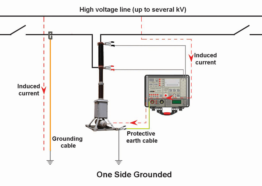
Figure 1: Circuit Breaker Test with One Side Grounded (above) and Both Sides Grounded (below)
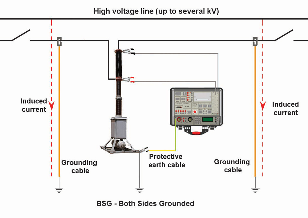
If both sides are grounded, applying conventional main arcing contact state detection methods is not possible because there is a parallel circuit through ground cables and the ground network. When both sides of the circuit breaker are grounded, modern test methods use a main circuit resistance measurement for the main arcing contact state detection during a circuit breaker operation. This procedure is similar to the DRM method.
When a circuit breaker is open, there is a closed circuit through the grounding cables and grounding system. Commonly, the resistance of this circuit ranges from a few mΩ to tens of mΩ. Arcing contacts are first to close and last to open the main circuit, so they define the closing and opening time of the circuit breaker. The resistance of arcing contacts ranges from a couple of hundred μΩ to a couple of mΩ. Thus, it is possible to detect changes in the recorded resistance curve at the instances of arcing contact separation. Based on this, breaker timing can be measured in BSG conditions. Unlike conventional methods using only low power dc voltage sources, the BSG method requires additional dc voltage with ampacity of a few tens to a few hundred amperes.
Power Source for DRM and BSG Methods
Portable equipment for measuring resistance using the DRM and BSG methods must have an integrated power source that will provide high current for testing purposes.
A high dc current power source can be realized in various ways. Lead-acid batteries were used as a power source for this method, but transportation cost, difficult installation in a portable instrument, and other technical reasons prevented wide use of lead and similar rechargeable batteries. Another way is to use energy directly from an ac mains supply using high-frequency dc/dc power converters. This solution provides continuous high dc current, but is dependent on the availability of the ac source on the mains supply; furthermore, power converters require more space in the instrument than some non-dispersible energy storages.
One such energy storage device is a supercapacitor (ultracapacitor or EDLC-electric double-layer capacitor). A supercapacitor has capacitance from a few hundred or thousands of Farads and voltage of a single cell from 2.3 to 3.0 V. Most of these components have very low internal resistance — in the order of milliohms — so it is possible to generate currents in the order of hundreds to thousands of amperes.
A supercapacitor can be charged from a low-power electronic source or from batteries (lead-acid, NiMH, Li-ion, and similar) with lower current (around 1 ampere), which requires longer charging time (up to one minute). Capacitor discharging can be performed with currents of up to hundreds of amperes in intervals up to one second.
High-power batteries such as lithium polymer (Li-Po) or similar also provide high-impulse dc current, which overcomes these shortcomings.
High-Power Battery Versus Supercapacitor
Solutions applying standard batteries and supercapacitors (Figure 2) have a few shortcomings:
- Long charging or recharging time, ranging from 10–130 seconds depending on the current level and duration of the test
- Significantly reduced supercapacitor dc voltage when the capacitor discharges, requiring constant recharging to provide the voltage level necessary for the desired current (e.g. >100 A)
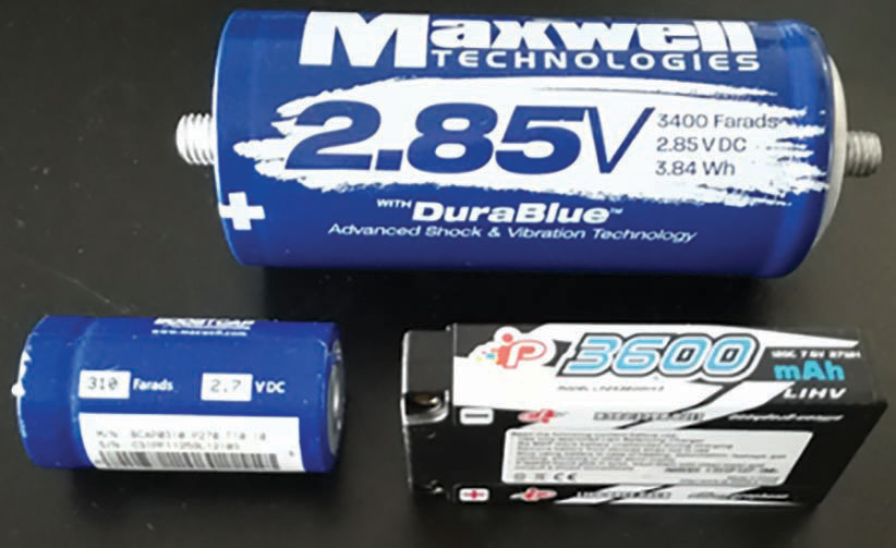
Figure 2: Supercapacitor 3400 F (top), Supercapacitor 310 F (bottom left), 3600 mAh High Power Battery (bottom right)
High-power batteries have higher capacity and lower demand for recharging and are suitable for installation in a portable test instrument.
Once charged, a high-power battery with the capacity of 3,600 mAh is capable of generating around 300 to 400 100A current pulses for 100 ms and uses lightweight current cables 10–20 meters long. The voltage level of the 100 percent charged battery is 4.2 V (single-cell 4.2 V; two serial connected cells 8.4 V, etc.), while a 30–35 percent charged battery cell has a voltage level of 3.7 V (7.4V for serial connected cells). That means voltage is reduced only 0.5 V when the battery is about 70 percent discharged. When connected in a series, these battery cells can be charged from a universal 100–250 V, 50–60 Hz ac mains supply adapter, but also from a standard car supply outlet (12 V).
A current regulator can be used to set the desired test current during the resistance measurement of the main circuit. It is also possible to use a voltage regulator to provide constant voltage on the output terminals of the device and to use the current measurement as a feedback value to set the desired current by controlling the output voltage.
Figure 3 shows the block structure of the proposed measurement and control system.
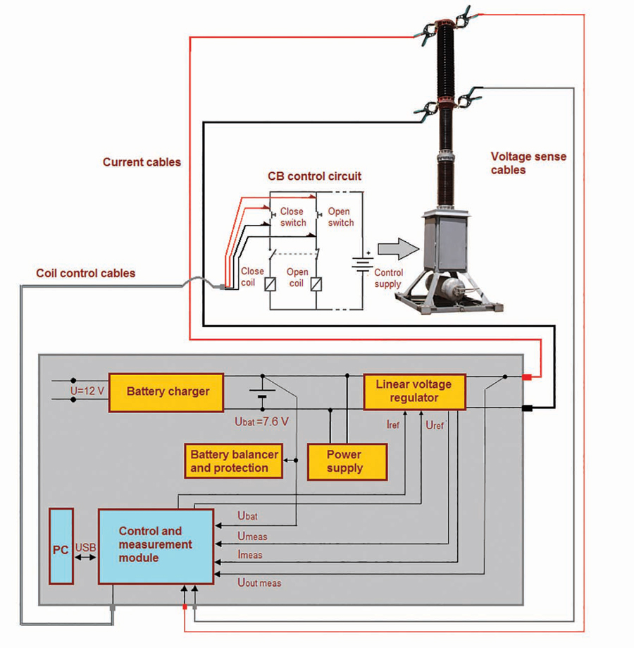
Figure 3: Block Structure of Proposed System
Method Verification on the Test Object
To verify the efficacy of this battery as a power source for DRM and BSG methods, a control and measurement module was constructed. Tests have been carried out on actual test objects (Figure 4).
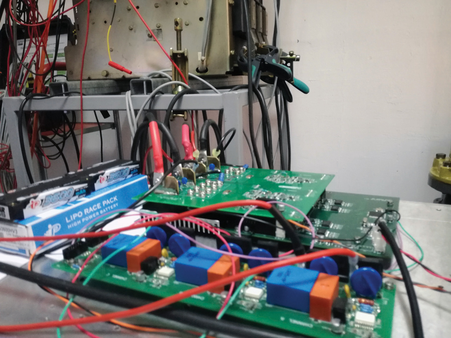
Figure 4: Constructed Control and Measurement Module
The test was conducted on a three-pole air circuit breaker, model AT-16, manufactured by Terasaki Electric Co. LTD, Japan. Simultaneous measurements recorded the test current and the voltage drop across the breaker’s main circuit. Current was recorded by measuring the voltage drop across a shunt resistor.
Breaker timing was measured from the instance of energizing the coil. For that reason, a coil control module was also constructed and connected to the main processing unit.
The test procedure can be described as follows:
1. Test preparation
- Set the circuit breaker in the closed position.
- Start regulating the current by increasing the output voltage of the voltage regulator.
- When the current reaches the desired value, store the current settings.
- Stop regulation.
2. Test
- Set the coil control and the measuring module to trigger waiting mode.
- Enable voltage regulation and set the output voltage to the previously stored value.
- Simultaneously start the measurement and issue the command to open or close the breaker coil (depending on the current breaker state).
- Record the data and disable voltage regulation.
Simple software for data acquisition (Figure 5) also had to be developed. Data acquisition was performed through the PC’s USB port.
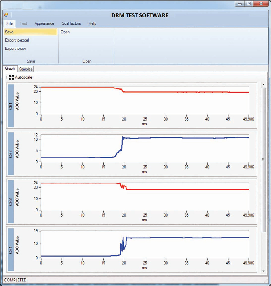
Figure 5: Data Acquisition Software
For easier data manipulation, the software incorporates an export option that supports several data formats (Excel™, .csv, etc.). The results were first exported in .csv; the data was then imported into MATLAB for further analysis.
The first tests were performed on the circuit breaker grounded only on one side. The DRM results, including current, voltage drop, and resistance for phase A are shown in Figure 6. It is not difficult to determine the moments of separation of the breaker’s main and the arcing contacts. Based on these points, parameter overlapping time can be determined and used to assess the arcing contact condition. The peak on the voltage drop graph during arcing contact engagement indicates high-resistance changes during the open operation, which further indicates a rough arcing contact surface, usually due to wear of arcing contacts. The test current was around 50A.
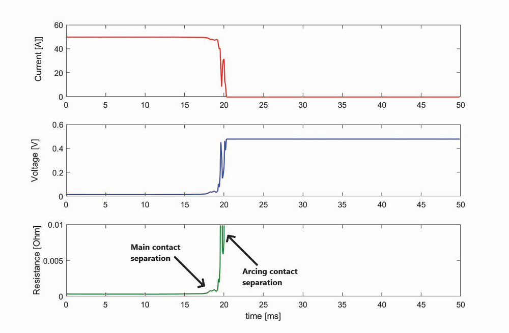
Figure 6: Current, Voltage Drop, and Calculated Resistance during Opening Operation — One Side Grounded
The breaker was then grounded on both sides, and the DRM test repeated. The measured grounding resistance was around 12–13 mΩ. Figure 7 shows the results for the same phase (A).
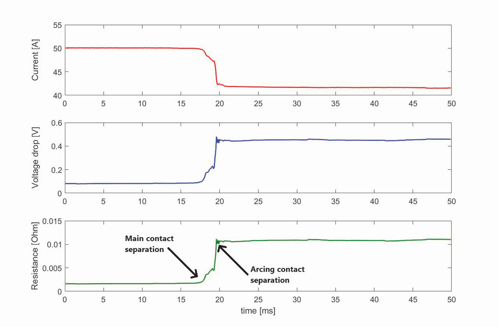
Figure 7: Current, Voltage Drop, and Calculated Resistance During Opening Operation — Both Sides Grounded
The moments of separation of the arcing and main contact are identical on Figure 6 and Figure 7, which means that the described method can be successfully used with one side grounded and with both sides grounded.
Next, several DRM tests were conducted on all three phases of the tested circuit breaker. To examine repeatability, the dynamic resistance graphics were overlapped for each phase separately. Figure 8 shows three of the graphs for each phase. The breaker was grounded on both sides.
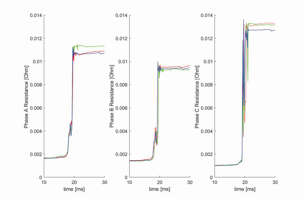
Figure 8: Overlapped DRM Results for Opening Operation on Phase A, Phase B, and Phase C
The results show increased bouncing in phase C, where grounding resistance had the highest value. However, repeat tests led to almost identical results for all three phases.
The proposed method can also be used to conduct a DRM test during close operation. Figure 9 shows the results. Arcing contacts touch around t=38 ms, while the main contacts close in t=40 ms after some bouncing. The initial current is around 42A, which corresponds to the ratio of the regulated voltage at the output terminals and the resistance of the serial connection of the current cables and the grounding resistance. As seen in the diagram, the current value goes up to 50A, representing the set current value for the breaker in the closed position.
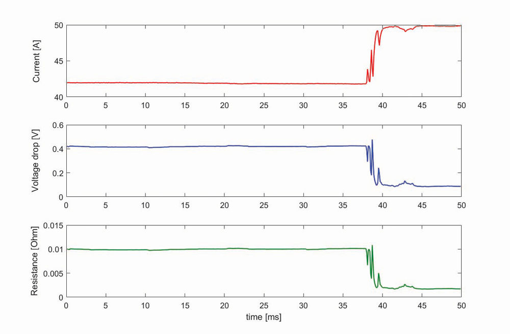
Figure 9: Current, Voltage Drop, and Calculated Resistance During Closing Operation Under BSG Conditions
In total, approximately 100 tests were performed on the test object without recharging the single battery. This proves the benefits of using high-power batteries during condition assessment of high-voltage circuit breaker main and arcing contacts.
Conclusion
High-power batteries (Li-Po or similar) are a good solution for generating dc current pulses for Dynamic Resistance Measurement and timing tests with a circuit breaker grounded at both terminals. The experiments show that these batteries can hold a steady voltage regardless of high discharging test currents.
These batteries are superior to similar solutions, as they now can be used as a building block of a handheld device capable of performing a large number of operations without single battery recharging. This reduces testing time and contributes to savings in test personnel work hours.
References
A. Secic and B. Milovic, DV Power–Sweden. “Dynamic Resistance Measurement Method Applying High DC Current,” CEATI Circuit Breaker Circuit Breaker Test & Maintenance WS, 2014, Palm Desert, CA, USA.
V. Mrdic, R. Levi. “Advanced Dynamic Testing of Substation Apparatus,” TechCon USA 2016, Albuquerque, NM, USA.
J. Levi. “A Simplified Method for Determining HV Circuit Breaker Contact Condition – Dynamic Resistance Measurement,” Doble Client Conference, Boston, MA, 2005.
IEEE Std. P510, Guide for Electrical Safety in High-Voltage Testing.
OSHA 29 CFR 1910.331 – 1910.335, Electrical Safe Work Practices.
R. Ostojic and B. Milovic. DV Power–Sweden, “New Requirements in Circuit Breaker Diagnostics,” NETA World — Spring 2014.
Maxwell Technologies, BOOSTCAP® Ultracapacitors, Product Guide.
 Adnan Šečić is an R&D Engineer at DV Power–Sweden. As a project leader, he is responsible for development of the circuit breaker analyzer and timer (CAT) device series. Adnan received his BS in electrical engineering and MS in electronics, electrotechnics, and automation (EAA) from the University of Sarajevo, Bosnia and Herzegovina, and is in the final stage of PhD studies at the Faculty of Electrical Engineering and Computing in Zagreb, Croatia.
 Radenko Ostojić is a test and diagnosis engineer at DV Power–Sweden in the field of circuit breaker testing and maintenance. He has been employed at DV Power since 2010 and works on the improvement of circuit breaker testing equipment and development of new methods for circuit breaker testing. Radenko’s area of special interest is testing of circuit breakers in enhanced safety conditions, which implies testing of circuit breakers with both terminals grounded. He earned his BS in electrical engineering at the University of East Sarajevo.
 Nijaz Hadžimejlić has been with DV Power since 2015. From 1977–1998, he was with the Department of Power Electronics and Motor Control, Institute for Computer Science and Control-IRCA, Energoinvest, Sarajevo. Nijaz was a part-time Teaching Assistant and Senior Teaching Assistant in the Department of Electrical Engineering, University of Sarajevo from 1984–1997 and was an Associate Professor from 1998-2015. He received his BS, MS, and PhD degrees, all in electrical engineering, from the University of Sarajevo. Nijaz’s research interests include power electronics converters, motor drive control for electric cars, and robotics. He is the author or co-author of over fifty technical papers.