
Verifying the functionality and integrity of a grounding system is critical to maintaining a safe workspace. Unfortunately, the tests used to achieve this goal, as well as the standards used to assess them, have required a specialized skillset, often leaving these tests done improperly or not at all. Now, with the industry progressing toward guided testing, new solutions make it possible for these tests to be performed correctly and accurately with limited test-specific training. Ultimately, this makes the difficulty of testing a ground grid similar to that of testing a transformer or circuit breaker. This article explains the purpose and theory behind grounding system testing, as well as an explanation of how the test is performed.
THEORY
During a ground fault, fault current circulates between the fault location and the substation source that is driving it. In order to establish a low-ohmic return path for the fault current, grounding systems are designed to allow a conductive low-ohmic connection between the soil and the neutral of the system where the fault is located.
In principle, a grounding system consists of conductive elements including wires, rods, etc. These elements have direct contact to soil and therefore allow a current to flow between the soil and the neutral. Each conductive element placed in the soil increases the surface area of the grounding system in contact with the earth and reduces the grounding system’s impedance. With each successive element added to the ground grid within a given area, the incremental benefit is reduced; however, it remains true that the more conductive elements in the soil, the better the grounding system is.
Figure 1 illustrates the potential in the event of a ground fault at the tower of an overhead transmission line. The return current through soil causes a potential rise of the grounding system and the tower where the fault occurs when compared to reference ground (illustrated here as the flat green plain surrounding the ground grid and fault location). Following electromagnetic field theory, the result of such an event is two upward and downward cone-shaped potential rises, as depicted in Figure 1.
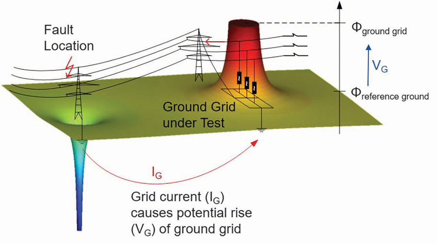
Figure 1: Potentials during a Ground Fault
The resulting potential rise, VG, is represented as the voltage between the grounding system and remote earth (a theoretical ground reference at an infinitely remote location, normally considered to be at zero potential). For testing purposes, remote earth is represented by the flat part around the grounding system’s potential rise, referred to as the reference ground. This zone is considered to be outside the area that is influenced by the grounding system.
To measure the connection between the grounding system and earth, ground impedance, ZG, is introduced:
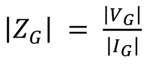
Equation 1
High ground impedance indicates a poor connection to reference earth. To reduce ground impedance, the grounding system must either be extended by additional conductive elements or repaired by replacing conductive elements that have deteriorated. This section explains how to determine the ground impedance.
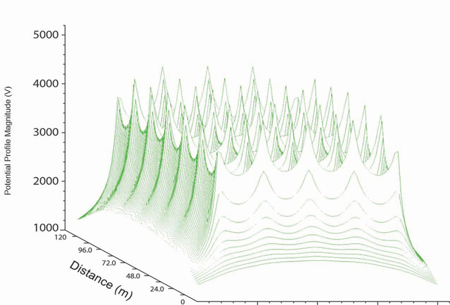
Figure 2: Potential Gradients of a Ground Grid
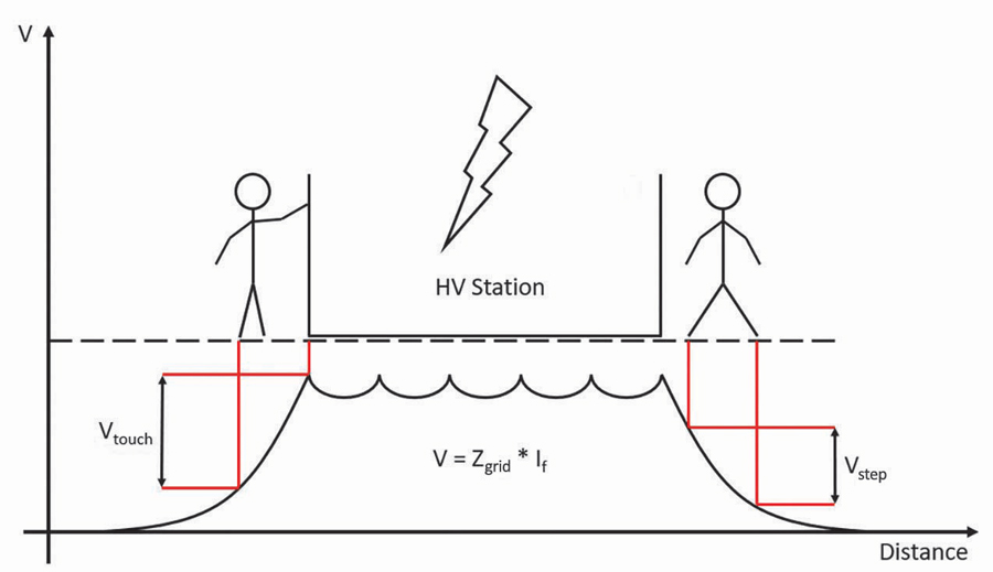
Figure 3: Step-and-Touch Voltage
Figure 2 and Figure 3 illustrate the potential rise of a ground grid in detail. In contrast to the simplified illustration in Figure 1, the potential contour inside the grounding system is not flat. Therefore, step-and-touch voltages must be considered both inside and outside the substation for personnel safety. A touch voltage is defined as the difference in potential between a grounded object and a location 1m away in the event of a ground fault. This scenario represents the worst case for a person touching this object; a maximum arm span of 1m is assumed. Similarly, a step voltage is defined as the difference in potential between two locations 1m apart from each other in the event of a ground fault. This scenario represents the worst case for a person being exposed to a step voltage by standing with his feet 1m apart.
To recommend limits for step-and-touch voltage, IEEE Std. 80-2013, IEEE Guide for Safety in AC Substation Grounding and EN 50522:2011, Earthing of power installations exceeding 1 kV a.c. define permissible body currents (Figure 4). IEEE 80 proposes three different limits (according to Biegelmeier and Dalziel) but doesn’t explicitly recommend any. Regardless of which limit is used, the permissible body current depends on the maximum fault duration; therefore, a higher fault duration results in a lower permissible body current. In both standards, the estimated body impedance used for the assessment of step-and-touch voltages is 1kΩ. Conveniently, this means that using Ohm’s law, the permissible body current shown in mA on the vertical axis in Figure 4, is also the permissible step-and-touch voltage in V.
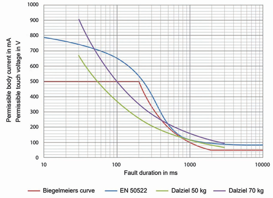
Figure 4: Permissible Body Currents and Step-and-Touch Voltages
Overhead transmission lines are usually equipped with a ground wire, which results in a parallel current path in the event of a ground fault. This means that a portion of the total fault current returns via the ground wire, whereas the other portion returns via the soil. This results in a lower ground potential rise, as well as lower step-and-touch voltages, since both are caused by the current flowing through the soil (grid current IG) and are not affected by current returning through the ground wire. The same applies to cables equipped with a conductive cable shield. This can be accounted for by using a reduction factor, which will be explained further on.
TEST TYPES
The two primary tests used to verify the integrity and function of a ground grid are ground impedance and step-and-touch voltage.
Ground Impedance Testing
The ground impedance test is used to verify the connection between the grounding system and its surrounding soil. There are several methods of performing the ground impedance test, but for the purposes of this article, we will focus on the fall-of-potential test method. Other methods such as the two-point method, three-point method, and staged fault tests used to determine ground impedance are not covered in this article due to their limitations. If more information is desired, these methods, as well as the fall-of-potential method, are explained in IEEE Std. 81-2012 Section 8.2.2.
The fall-of-potential test procedure is relatively simple and can be made easier by using a test set that provides a guided workflow. A current is injected into the soil using a current probe at a distance from the grounding system under test. IEEE Std. 80 recommends this distance to be at least five times the largest dimension of the grounding system. When the test current is injected, the voltage is measured at several points along a line perpendicular to the test current injection and is used to calculate the impedance between each test point and the grounding system under test (Figure 5).
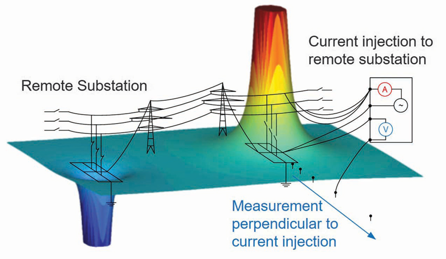
Figure 5: Fall-of-Potential Measurement Using an Existing Line for Injection
Although it is possible to measure voltage in the same direction as the current injection, it introduces the possibility of interference caused by the cable being used for that purpose. Testing perpendicular to the current injection path results in reliable measurements with less risk of interference. Using these impedance measurements, we can then create a graph showing impedance versus distance so that we can identify the point where the measurement stabilizes. This flat portion of the curve, generally determined by three consecutive measurement points with little to no variation in results, represents the measured impedance between the grounding system and remote earth. Since we already identified remote earth as a theoretical ground reference, for the purpose of this test, it is essentially a distance at which the earth potential is unaffected by the ground potential rise of the current injection probe or the ground grid.
The difficulty of this test comes from the size of the area being tested and the distance between test points rather than the complexity of the theory or testing process. As mentioned above, IEEE Std. 80 references a typical distance of at least five times the largest dimension of the grounding system between the grounding system and the current probe. For small grounding grids, this can easily be achieved by rolling out a cable and driving a current probe at the desired distance. For larger grounding systems, however, this becomes significantly more difficult since traveling the necessary distance to place the current probe often requires crossing roadways, private property, or other obstacles. In addition to placing the current probe, you also need to take voltage measurements at various distances from the grounding system, ideally in a direction perpendicular to the current injection cable.
One way to overcome the difficulty of placing a current probe is to use a transmission line for your current injection. By grounding the line at a remote substation and injecting at the local end, we are able to use the grounding system of the remote substation as our current probe, giving us a better connection to ground than would be possible with a basic stake and eliminating the hassle of running a cable out to the required distance. In addition to improving the ground connection and simplifying the setup, this method often makes it possible to increase the distance to the current probe, which reduces the possibility of the results being affected by the current probe or grounding system. In other words, increasing the distance between the grounding system and the current probe also increases the feasibility of measuring a stable reference to remote earth.
Although injecting on a transmission line increases accuracy and reduces setup time, it is not without its difficulties, and several things must be considered. First, injecting on a transmission line requires the line to be taken out of service for the duration of the test. This in and of itself may prevent using this method in some situations. If the line can be taken out of service, the next thing that must be considered is safety.
To protect personnel from any potential hazards associated with connecting to a transmission line, such as induced voltage, ground faults, and lightning strikes, a few precautionary measures should be taken. For the purpose of the test, the remote end of the line will be grounded and will not need to be removed until it is put back in service. The local end of the line, however, will need to be isolated from ground during the test. To maintain safety while performing the tests, it is recommended to use a test device that is not only galvanically isolated from the transmission line but also provides a method for shunting current from the transmission line to ground in the case of a fault. By using a test set with these features, the test can be performed while maintaining a level of safety near to that of having the line grounded at both ends.
It should be noted that for smaller grounding systems, as well as situations where taking a transmission line out of service is impractical, it may be easier to perform the fall-of-potential test using a current probe rather than a transmission line, and the results are similar in accuracy as long as care is taken to ensure the probe is a sufficient distance from the grounding system. Having the ability and equipment to perform the test using either method can be very beneficial in terms of flexibility.
Regardless of the method used, determining the correct test current and having a device capable of supplying it is a must. A few key things must be determined. The first question becomes how to get a reliable measurement result while avoiding the noise and interference from surrounding equipment. This is easily solved by testing at frequencies above and below the line frequency and interpolating between these test points to determine the result. Utilizing three test points allows for a more accurate interpolation, as the frequency response is not necessarily linear.
Another thing to consider is the impedance of the injection path, especially when injecting on an existing transmission line. Knowing the impedance and being able to adjust the output of the test device allows us to maximize the test current without exceeding the output power of the test set.
Once the test setup is complete, the next step is to take the measurements. There are several options, but the general process is to measure the voltage at various distances from the grounding system by running out a wire, placing a probe, and measuring the voltage between the probe and the grounding system. This is historically done by using the test set located in the substation that is supplying the current injection.
Alternatively, devices are available that perform the measurements using a handheld unit that can feed the results back to the main test set. This eliminates the difficulty of communication between the person placing the test probe and the person running the test set since both are in the same location. Additionally, a handheld device has the benefit of being in the same location as the test point, which makes it possible for that unit to utilize GPS location and add the location data to the test results, saving the operator from having to manually measure the distance between test points. These test points should be taken roughly every 50m, with the distance between points being reduced within the 100m closest to the ground grid.
These results are then analyzed by multiplying the measured ground impedance by the maximum grid current to determine the ground potential rise and comparing this to the applicable standard. EN 50522 states that if the ground potential rise is less than double the permissible touch voltage, the step-and-touch voltage measurement can be skipped. IEEE Std. 80, on the other hand, doesn’t recommend any limits for ground impedance or ground potential rise. If reference values obtained by ground-grid simulation are available, they could also be compared to the measured fall-of-potential to cross-check the simulation and measurement results.
Step-and-Touch Voltage Testing
For step-and-touch voltage measurements, injection of the test current remains the same as for the ground impedance measurement. The only difference is that the voltage measurement is now performed at selected locations both inside and outside the substation.
IEEE Std. 81 recommends measuring touch voltage with a high-input impedance voltmeter by using a rod that is driven at least 8 inches into the soil. By doing so, the measured touch voltage is higher than the touch voltage a person would be exposed to. Similarly, to measure step voltage, two rods are driven into the soil 1m apart. For assessment of step-and-touch voltages, IEEE Std. 80 considers additional resistances that lead to higher permissible step-and-touch voltages than shown in Figure 4. IEEE Std. 80 Section 8.3 provides the exact equations to calculate permissible step-and-touch voltages.
EN 50522 suggests the personnel simulation method, which is performed by measuring the touch voltage across a 1kΩ resistor and using a metal plate to simulate bare feet 1m away from the object. The plate must have dimensions of 20cm x 20cm and be loaded with at least 50kg, ideally a person who steps on it. EN 50522 also recommends wetting the soil under the metal plate to simulate the worst case. To assess measured touch voltages, the limits in Figure 4 apply after the measured voltage has been calculated by taking into account the maximum current to earth, IG, as shown in Equation 2. Table 1 within EN 50522 outlines the calculation of IG for every neutral configuration. Measuring and assessing step voltage is not mentioned explicitly in EN 50522.
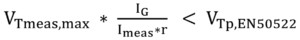
Equation 2
Reduction Factor
Reduction factor measurement determines the portion of the injected test current that is returning via the soil rather than the ground wire. To do this, a test current is injected, the same as for ground impedance measurement, and the return current is measured by using a Rogowski coil that is wrapped around a grounded conductor or a similar method. This grounded conductor could be the connection of the ground wire to ground, for example. If the entire return current can’t be accounted for in the first measurement, the measurement is repeated at all conductors that are serving as a return path. The individual currents must then be added by considering their phase angle in order to obtain the true value for the overall return current. The reduction factor is then calculated according to Equation 3.
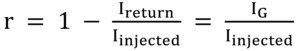
Equation 3
The standard does not define limits for assessing the reduction factor. One way to assess the reduction factor measurement is to check if the measured reduction factor is lower than the reduction obtained by simulation. If this is true, the grid current resulting from the simulation is even more conservative than the grid current resulting from the reduction factor measurement. Alternatively, the measured reduction factor can also be used to directly determine the step-and-touch voltages according to Equation 2.
CONCLUSION
Despite a reputation for being difficult, grounding system testing can be performed by using a guided approach driven test set and readily available training resources to yield reliable and accurate results without extensive test-specific training.
 Logan Merrill is an Application Engineer at OMICRON electronics Corp USA. He received a BS in electrical engineering technology from the University of Maine.