

Solar farms, which are exposed to the elements, are especially at risk for failure and require dedicated electrical maintenance. Good grounding is essential, as the panels produce high DC voltages that can be sources of shock and fire, as well as induced voltages and electromagnetic interference on lines.
With respect to grounding, there are two types of photovoltaic (PV) systems: floating and earthed or grounded. In a floating system (Figure 1), non-current-carrying conductive parts are connected to ground in order to prevent dangerous or destructive voltages from developing.
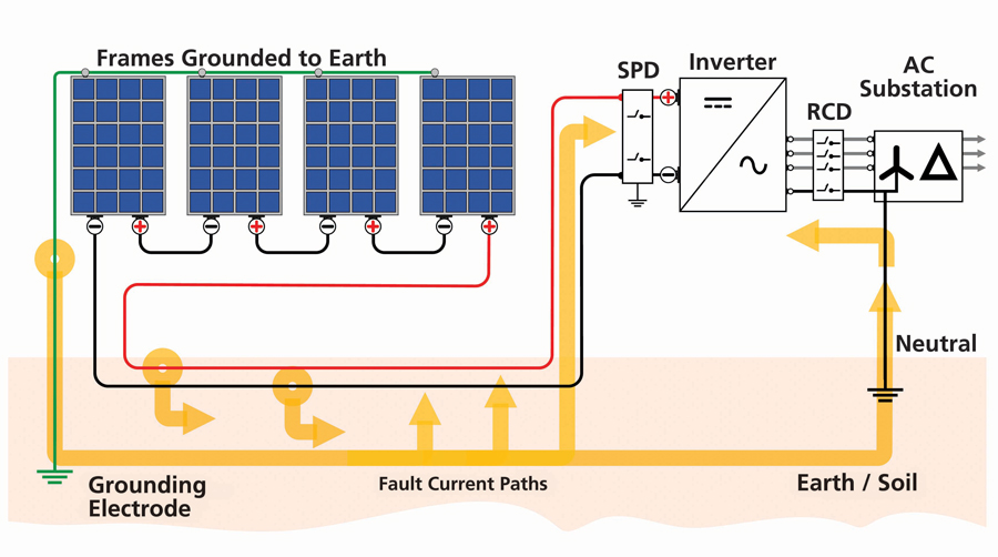
Figure 1: Floating Non-isolated PV System
Solar arrays sometimes use Class II modules and Class II DC cables and connectors. These are connected to the mains through an inverter using an isolation transformer (Figure 2).
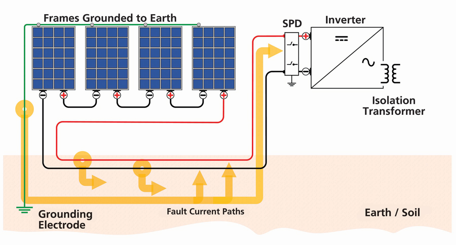
Figure 2: Floating Isolated PV System
This configuration leaves the array frame floating. Floating systems are sometimes preferred in order to protect the safety of low-voltage panels and other sensitive equipment from line disturbances such as ground faults.
Faulty equipment or damaged insulation can produce accidental ground leakage. Such systems require specially listed inverters with array fault-detection capability, as well as wiring protection, overcurrent protection, disconnecting devices, and ground-fault protection in both DC conductors.
By contrast, grounded (or earthed) systems connect a current-carrying conductor in the electrical system to ground potential (Figure 3). A bonding to earth is made to any of the live DC current conductors.
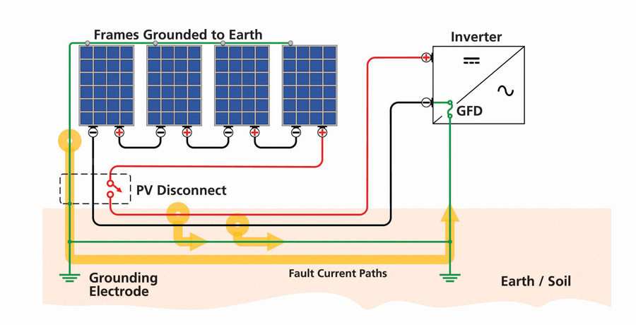
Figure 3: Grounded PV System
Planned ground leakage occurs as a consequence of the design of the array. PV systems by default should be equipment-earthed (first example) and, in the great majority of cases, should also be protected with a system ground.
In such systems, a ground-fault condition is detected by current flow in the grounded conductor and electrode, opening the circuit; the inverter displays a ground-fault alarm. The connection between the grounded conductor and the grounding electrode is normally made through the ground-fault protection device.
Lightning strikes are common causes of damage to solar arrays. There may, of course, be a direct hit, but a nearby strike may also induce surges on both the array conductors and the AC cables.
TESTING AND MAINTENANCE
It is apparent that PV systems must be regularly tested and maintained against these potential problems of stray ground currents in order to remain both safe and fully operative.
Record keeping is invaluable from the time of initial commissioning and subsequently upon changes and modifications. Being able to compare system changes to stored records enables maintenance staff to recognize potential or developing problems in time to head off developing issues before they become inordinately costly or dangerous. Such a thorough and conscientious program typically consists of six tests.
Visual Inspection
What may seem like a no-brainer is in fact a valuable and often short-cut means of effective maintenance. Look for incomplete installation details and validate sufficient compliance with local applicable standards. These shortcomings can be inordinately costly if left unattended until well into the life span of the array. Visual inspection can spot physical damage along with modification or degradation of equipment from the effects of environmental conditions like temperature extremes, dust, corrosion, and moisture. Often situated in remote locations, solar arrays may also be subject to considerable damage from rodents chewing wires and birds building nests in the structure.
Continuity
Continuity testing verifies that adequate low-resistance bonding has been established between module frames, conductors, structures, connectors, and other terminations of de-energized circuits to the grounding system. Simply bolting or crimping metallic components together is insufficient to guarantee that the required current flow can be accommodated without overheating, sparking, or other dangers — not to mention the possibility that in the complexity of a large grid, some connections and terminations may be missed altogether.
IEC 62446, Photovoltaic (PV) Systems — Requirements For Testing, Documentation and Maintenance — Part 2: Grid Connected Systems — Maintenance of PV Systems is a reliable standard to apply. The grounding electrode conductor should be verified as continuous, and the viability of irreversible splices, welds, and other connections should be assured by accepted methods. The connection of the grounding conductor to the ground electrode (ground rod) must also be verified, as this may be called upon in fault situations to accommodate currents well above system levels. Continuity bond testing of metal cable trays, enclosures, frames, fittings, and other components that may serve as grounding conductors in fault situations should also be included.
Electrical continuity can also be lost due to inadequate mechanical installation. Be sure to test electrical continuity between the grounded PV array source circuit and output circuit conductors to the ground electrode conductor. Don’t forget to ensure that this bonding is re-established when equipment is removed for service or replacement.
Polarity
Correct polarity, as well as correct termination for equipment, should be verified for PV DC circuits utilizing the DC circuits. This is accomplished by measuring the voltage on energized circuits prior to closing disconnects and operating the system. The points in the system where this test should be implemented are PV modules, PV source and output circuits, disconnect means, battery and charge controller circuits, inverter input terminals, and electrical loads.
Every source circuit and the entire PV power source should be tested accordingly before connecting to any DC equipment. Accidentally reversing polarity of an array connection to a battery is a serious potential danger leading to accidents, equipment destruction, and even danger to lives.
Voltage and Current
Confirm that the array and system are operating according to expected commissioning and equipment manufacturer’s specifications. DC and AC voltage and current are tested before closing disconnects and starting operation. AC voltage and phasing are verified at the utility supply, inverter ac terminals, and disconnects. DC voltage and polarity for the PV array source and output circuits as well as the DC disconnects are also checked. In addition, DC voltages and polarities on batteries, battery chargers, and controllers should be checked.
These tests are of two types: open-circuit voltage and short-circuit current.
- Open-circuit voltage testing is also performed to prove polarity of the array source. Suitable testers must be capable of withstanding voltages over 600 V AC and DC. Typical differences in voltage values within 5% can be expected between strings within an array. Damage and errors like inappropriate array cabling and damaged modules or bypass diodes can be indicated by producing lower voltages. These values can also be affected by temperature and irradiation at time of testing, with changes in the range of 2.5% per 10°C.
To identify faulty strings, first verify the open voltage of all strings. Then divide the voltage of a good string by the number of modules in the series. This determines the module voltage. For example:
– If the voltage of a string of 10 modules in series is 500 V, then the voltage of each module is 500 ÷ 10 = 50 Vdc per module.
– If measuring on a faulted string of 50 modules, the voltage equals 400 V and the voltage per module is 50 V, then 400 ÷ 50 = 8. Therefore, the fault may be 8 modules back from the high-voltage (output) side of the string. - Short-circuit current testing (Isc) requires a tester capable of standing DC currents greater than 10 A, plus using suitable shorting devices so as to perform a test safely. The short-circuit current of a PV array is proportional to the solar irradiance on the system. This test should be performed briefly under clear skies with the PV modules free of dust or shade. Acceptable differences should fall within 5% between each PV string.
Insulation Resistance
Insulation degradation is a common cause of electrical failure anywhere and everywhere in the electrical grid. Solar fields are no exception. Testing must be done within PV arrays and system circuits. Such testing is performed by applying a DC voltage, normally anywhere from 50 V to 5 kV depending on the point in the system — between conductors or from conductor to ground. This is always done while de-energized. The insulation stands between the two poles of the applied voltage, and any current flow is an indicator of the condition of the insulation. In healthy insulation, this would be in pico amps and above the range of many common testers. But as insulation deteriorates, this current, called leakage, rises and becomes measurable, typically in megohms. By the time it reaches 5 mA, human shock level, the equipment has deteriorated and needs repair or replacement. This is generally around 1 megohm or higher for systems with operating voltages of 120 V and above. For systems operating at voltages lower than 120 V, 0.5 megohms and above are acceptable.
Environmental conditions such as sunlight, moisture, gnawing animals and insects, mechanical impacts, and even normal operation all contribute to wear down the quality of insulating materials. Bonding connections are left in place while surge suppression is removed from the circuits. Make sure there is reliable electrical and mechanical contact between test leads and the circuits under test. Some connections may require grinding or filing. Of great importance is to discharge stored capacitance at the end of the test. Enough energy can be stored to be lethal; fortunately, all good-quality modern testers perform this potentially life-saving function automatically.
Such testing can be performed positive DC conductor to ground, negative DC conductor to ground, or between the shorted positive and negative conductors to ground. Suitable shorting devices are needed to perform the test safely. In floating systems where modules and structures are not provided with metallic frames with a bonded connection to earth, this test should be performed between array cables and ground and between array cables and frame.
Earth Leakage Current Testing
Systems equipped with residual current devices (RCDs) or ground fault circuit interrupters (GFCIs) can be tested for nuisance tripping. Such devices monitor current flowing in line conductors and compare it to return current in the neutral. If the difference in currents exceeds the sensitivity setting of the device in mA, the device will trip and open the circuit. A clamp-on ammeter is clamped around the line and neutral conductors separately. The difference between the two readings is the earth leakage.
CONCLUSION
The enormity and complexity of solar fields makes them a special challenge to maintain. They may appear static, but electrically, they are just as dynamic as visibly operating equipment. A dedicated electrical testing and maintenance regime is in order. Remember to utilize test equipment that includes storage and downloading capabilities. Keeping a well-organized electronic file of tests and results can turn a potentially chaotic situation into a model of effective maintenance and prevention.
 Jeffrey R. Jowett is a Senior Applications Engineer for Megger in Valley Forge, Pennsylvania, serving the manufacturing lines of Biddle, Megger, and Multi-Amp for electrical test and measurement instrumentation. He holds a BS in biology and chemistry from Ursinus College. He was employed for 22 years with James G. Biddle Co., which became Biddle Instruments and is now Megger.