
As part of the electrification of a facility, it is commonly thought that merely connecting the system to a driven ground rod means that the building is grounded. It’s not that simple. By pure luck, such an approach may indeed work. But the considerable value of the building, the efficiency of operation, the wealth of information and knowledge that is stored and transferred, and most of all the safety of personnel should not be left to luck.
Considerable variables are involved in establishing a good ground — that is to say, a ground of sufficiently low resistance so that the electrical system will operate at desirable or specified levels of efficiency and safety. To put it into perspective, the majority of electrical work is done on copper, a well-known quantity in terms of specifications and properties. Even insulating materials, though much more varied than copper, are composed of well-known formulae.
By contrast, soil resistivities (Table 1) can range in value from a few hundred to a million ohm-centimeters (Ω-cm). Indeed, on the low end of this scale, simply driving an 8- or 10-foot rod may be sufficient. But for more difficult soil types and local conditions, reaching specification may be a real challenge.
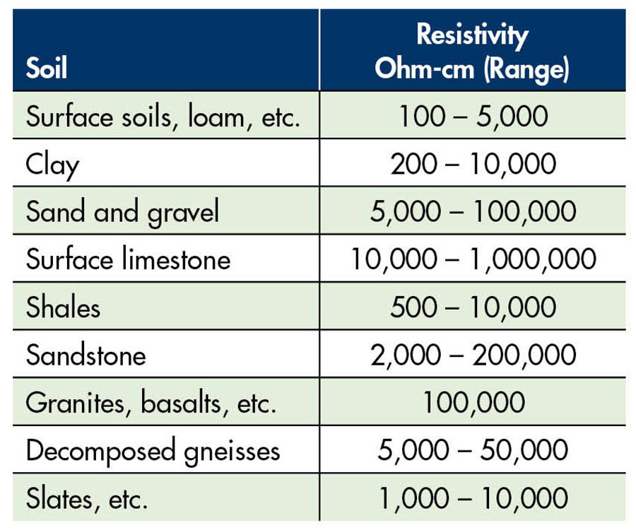
Table 1: Typical Soil Resistivity
GROUNDING MATERIALS
The first line of defense is the grounding electrode — the metal that is installed in the earth to which the grounding conductor or conductors are attached. Fault current, it is hoped, will find this the path of least resistance in going to ground and back to the utility that generated it or, in the case of lightning, equilibrium with the clouds. This is obviously preferable to traveling through equipment — or worse, people. Putting more metal in the earth is the most common remedy. The more contact the electrode has with the surrounding soil, the lower the resistance. Imagine a mob of people escaping a building fire; two doors are better than one.
Two general methods of getting more metal into the earth are to a) go deeper or b) laterally expand the size of the grid. There are practical arguments on both sides, but overall, going deeper is preferable…especially if you hit water table. Of course, water is a good conductor, and water table can provide a constant low-resistance path. The water table can drop over time, however, so periodic maintenance checks of the rod’s resistance must be taken (Figure 1).
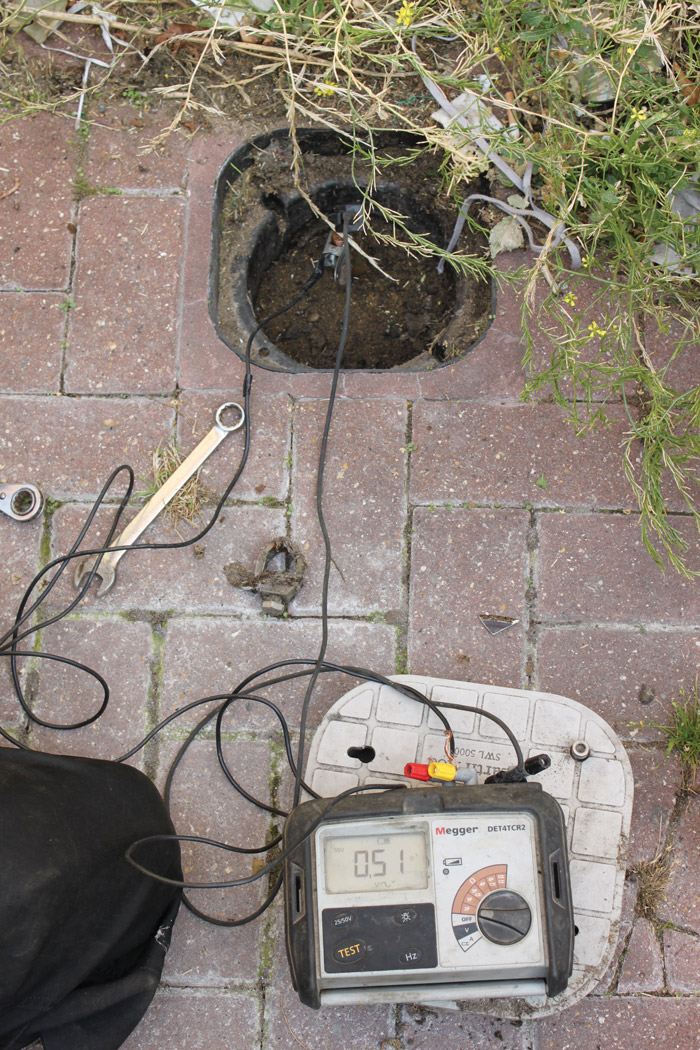
Figure 1: Maintenance Testing a Ground Rod
The major disadvantage to deep-driven rods is that they are comparatively expensive. They can be installed by coupling additional rods and driving the electrode deeper, but in more difficult hard-ground terrain, it may be necessary to drill a bore hole and backfill it with a conductive material around the rod.
An alternative to a deep-driven rod is to expand the electrode laterally. The easiest way to do this is to add more rods, not coupled on top of each other as in deep-driven, but expanded into an interconnected parallel grid. Additional rods should always be spaced at least as far apart as they are deep. This is so their electrical fields do not overlap and cause the two to begin performing as a single rod. This defeats the purpose of the added rod.
Generally, a second rod will decrease the resistance by about 40%. After that, though, it’s not so easy. Additional rods yield progressively smaller decrements until the exercise becomes counterproductive. Nonetheless, it is common practice to continually drive and test until spec is achieved.
Metallic grounding meshes or horizontal bars welded into a grid can also be used. These may be useful in areas of shallow bedrock where extensive excavation is prohibitive. But in cold climates, be sure any such structures can be buried below the frost line. Freezing immobilizes the dissipation of fault currents just as it does in a car battery.
OTHER MATERIALS
Thus far we’ve examined making the electrode larger or driving it deeper. These are the most common methods of grounding an electrical system to meet an imposed specification. But with the enormous variability of soil resistivity and local conditions, these methods can be challenged and may not be adequate. A number of specializations have been devised to meet the worst of conditions. One has already been mentioned: drilling a bore hole for a deep-driven rod and backfilling it with conductive material.
One of the most widely used materials is bentonite. Named for its discovery near Ft. Benton, Montana, bentonite is a mined material formed by the weathering of volcanic ash in seawater. It has the useful property of holding water molecules in a lattice structure that retards desiccation (unlike moisture in soil), which thereby maintains the grounding electrode in a steady and favorable environment for passage of current. Under severe conditions, bentonite may develop cracks and recede from the electrode, so synthetic variants are also available.
Ground enhancement material composed of Portland cement and a carbon-based conductive material (commonly known as GEM) is also widely used.
Improved materials for surrounding or encasing a ground electrode have more recently been developed. These appear on the market under various trade names, each with its own formulation aimed at promoting conductivity while retarding desiccation, cracking, and reduced contact with the electrode.
A representative formulation is based on natural clay, not carbon-based, and with neutral pH so as not to corrode the electrode even under prolonged contact. These materials can be hygroscopic, capturing moisture from the surrounding soil and holding it in a conductive lattice. A resistivity of 0.6 Ω/m is characteristic. Such materials can exhibit a capacitive effect in absorbing the high rise time of lightning strikes. A representative specification is 1,682 V/688 A for 500 ms. An NSF Standard 60 rating indicates to inspectors that the material is in conformance with environmental protection regulations. Systems have been known to remain effective for 50 years. Theft reduction is an added benefit, as the hardened conductive material makes extraction difficult.
CHEMICAL TREATMENTS
The soil itself can be chemically treated. Lowering the resistivity around the ground rod will promote current flow and lower the resistance of the rod to surrounding soil, possibly bringing it within the desired specification. Common materials are magnesium sulfate, copper sulfate, and rock salt. They can be applied in a trench dug around the electrode (Figure 2).
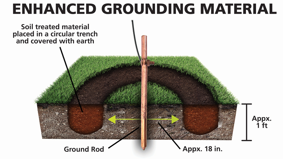
Figure 2: Application of Grounding Materials
But there are caveats. Rain and other weather conditions will slowly leach away the applied materials, so they must be regularly assessed and replenished. Depending on the porosity of the soil and amount of rainfall, it could be years before the treatment needs to be replaced.
Chemical treatments can also attack the electrode; magnesium sulfate is the least corrosive. Soluble sulfates can also attack concrete, so it must be kept away from building foundations. This poses a potential problem with lightning protection, where a short, straight path directly into the earth is most effective. EPA and local environmental regulations must also be considered. Industry standard parameters are covered in IEC Standard 62561-7, Part 7: Regulations for Earthing Enhancing Compounds.
ELECTROLYTIC GROUNDING SYSTEMS
Also in use are electrolytic grounding systems, where the rod itself is an active part of its environment. Hollow rods with breather holes extract moisture from the environment, convert it to salt water to provide greater conductivity, and gradually leach it into the surrounding environment to create a constant low-resistance path into the soil (Figure 3). More than replenishing soil moisture, the system creates electrolytic roots that further enhance the capability of the electrode to dissipate dangerous fault currents safely.
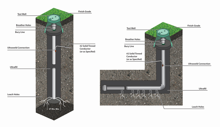
Figure 3: Specialized Rods Extract Moisture from the Environment
These systems are available as vertical rods for deep-driven electrodes and L-shaped rods for shallow bedrock where deep-driven electrodes would be cost prohibitive.
SOFTWARE SOLUTIONS
A more efficient and less time-consuming method is to design the system beforehand using dedicated software. Some are available at no charge from companies offering grounding materials such as rods and meshes. A four-terminal ground tester is needed to measure the resistivity of the local soil. The data will be entered in the software, along with the resistance value the grid must meet, plus a few qualifying questions. The software will then design and display an appropriate system: x number of rods laid out in a pattern.
CONCLUSION
With the enormous range of earth types and soil resistivities alluded to in the beginning of this article, any given site may or may not require heroic efforts to install an effective ground. However, such instances are not uncommon.
Many common soil conditions preclude simply driving a rod. For example, coastal loams such as those found along the Atlantic seaboard tend to be forgiving, but rocky and mountainous soils often call for more elaborate systems. Sandy soils such as in deserts and along seashores are also difficult. Grains of sand tend to have microscopic air pockets that do not conduct well. Sand does not retain water well and, in the passage to greater depths, electrolytic minerals that aid current flow get washed away.
Therefore, poor grounding conditions are not at all uncommon and may call for special accommodations in designing and installing the electrode. Don’t just drive a rod and walk away. Take a resistivity measurement first, and hope that it’s low.
REFERENCE
XIT Grounding. Product Catalog, Version 2022V1, 2022. Accessed at https://vfclp.com/lyncole/.
 Jeffrey R. Jowett is a Senior Applications Engineer for Megger in Valley Forge, Pennsylvania, serving the manufacturing lines of Biddle, Megger, and Multi-Amp for electrical test and measurement instrumentation. He holds a BS in biology and chemistry from Ursinus College. He was employed for 22 years with James G. Biddle Co., which became Biddle Instruments and is now Megger.