
All networks are susceptible to problems that affect communications. One consequence of a fiber optic system’s high bandwidth, long distance capability, and security is the extreme dependence of users on the non-stop operation of these systems. Because they can transmit large amounts of data long distances with immunity from signal degradation and extremely high reliability, these systems usually carry the most critical data.
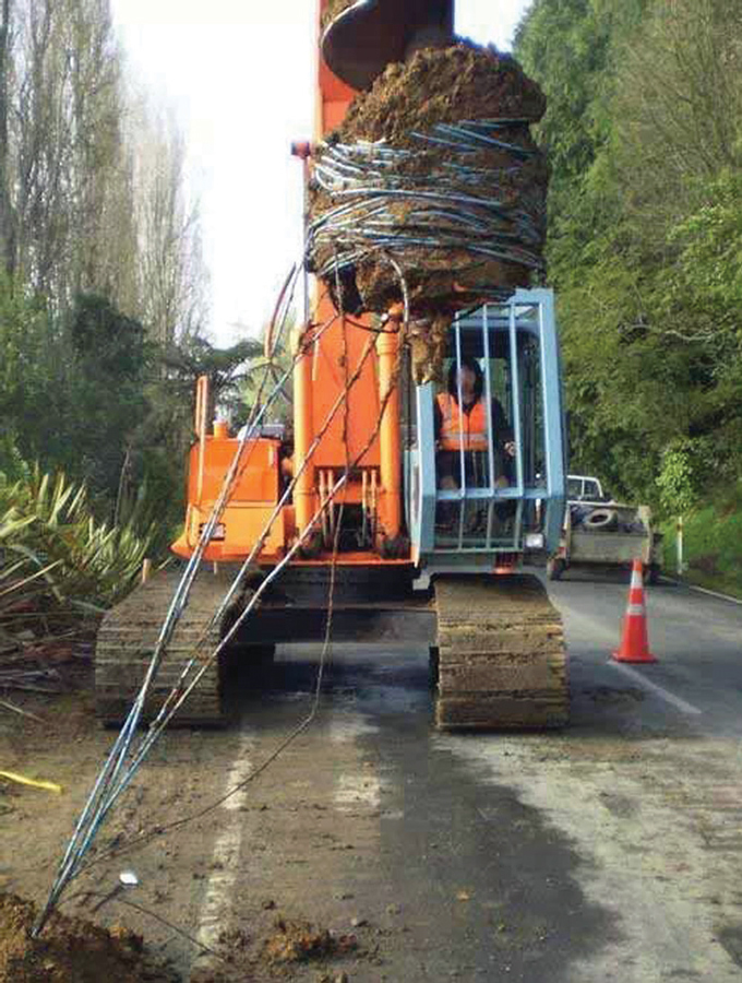
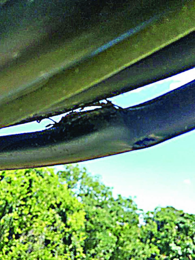
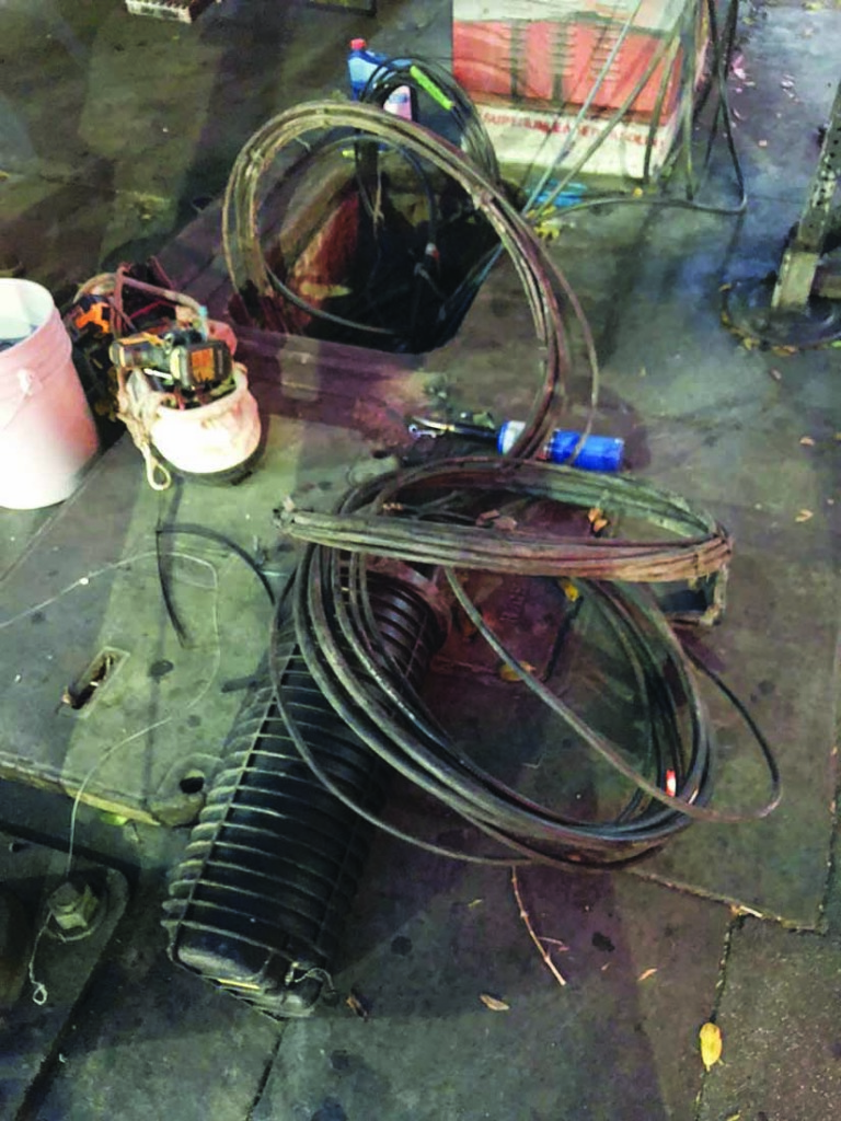
Damage from an Auger
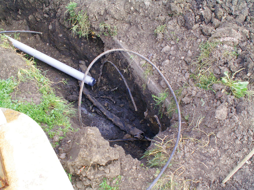
Damage from a Backhoe
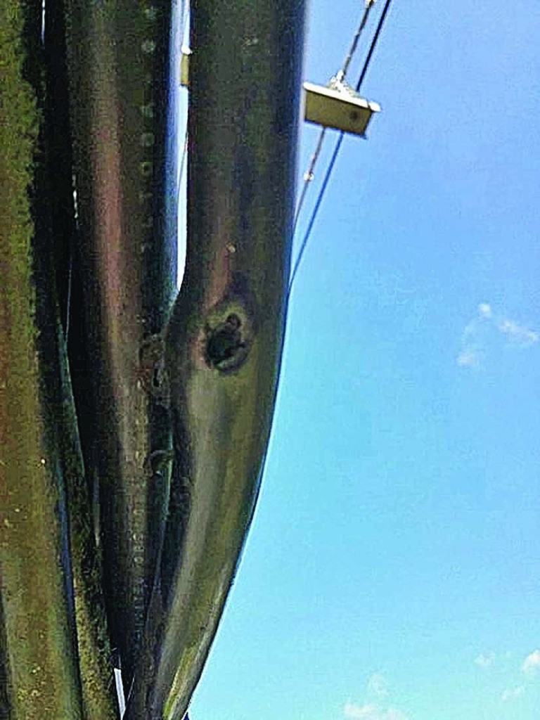
Damage from Gunshots
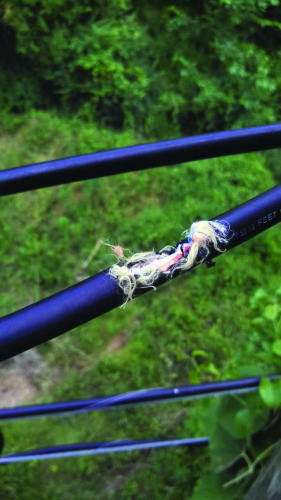
Squirrel Attack
Damage from Gunshots
Fortunately, fiber optic cable plants are very reliable and need no routine maintenance. We tell network owners that once the network is installed and tested, lock it up and keep all unauthorized personnel away from it.
Network operation does not require periodic testing because most equipment has built-in self-testing that monitors link errors and informs you of problems before they become serious. If your cable plant has spare fibers — it should — they can be used to periodically test the cable plant without disturbing the network.
What Goes Wrong?
It’s a fact of life: When fiber optic systems fail, it’s mostly due to accidental damage. I remember telling a group of network managers that in the fiber optic industry, we say the most common cause of failure is backhoe fade. A member of the group replied, “I’m from Bonneville Power, and our most common problem is target practice.” There are, in fact, many potential problems.
- Underground cable damage from construction dig-ups or directional boring
- Flooding during storms or ice in winter in manholes, hand-holes, or poorly sealed splice closures
- Aerial cable damage from vehicle accidents, shootings, animals, ice or storms, and vandalism
- Cutting the wrong cable when removing older cables indoors or out
- Breaking patchcords or connectors during moves, adds, or changes
- Getting connectors dirty or not cleaning dirty connectors properly before use
- Misconnections or polarity mismatches when connecting transmitters
- Breaking fibers in splice trays or kinking cable tubes in splice closures when building or upgrading networks
Sadly, there are even instances where disgruntled company employees sabotage links. Even personnel taking visitors on tours have unplugged a connector on an operating link.
Most of these problems affect outside plant cables, but premises cables are still susceptible to damage. With the current push by landlords to remove abandoned cables to comply with the NEC, the likelihood of damage is much higher as workers cut out the old cables.
Design for Reliability, Prepare for Restoration
We always tell network owners and operators that preparing for restoration starts at the design phase of the project. Communications system reliability depends on a design that has lots of margin, spare fibers in the cable plant, and diverse routing for traffic in case something does happen on a link.
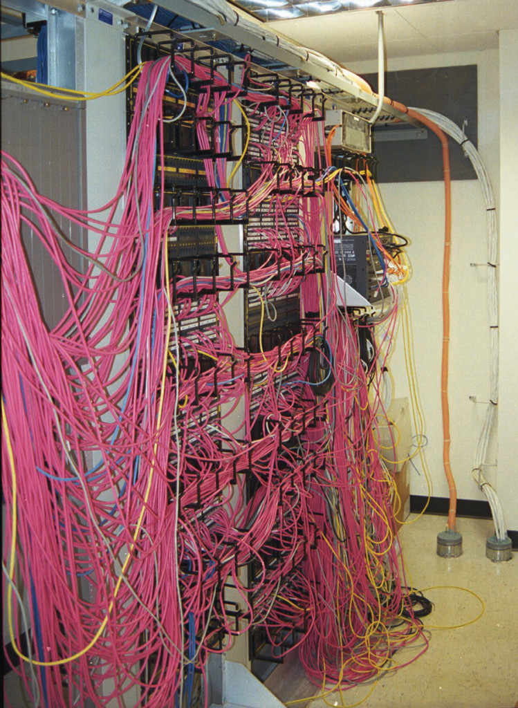
Moving cables in a typical patch panel without damage can be a challenge.
Telecommunications companies usually build route diversity into their network so a problem on one route will allow simply switching to another. Many systems also run backup links on spare fibers ready to switch over if one link fails. Critical systems in utility substations or control rooms should also have redundant connections on diverse routes to ensure connectivity in case of accidental damage. In 1975, the Browns Ferry Nuclear Plant nearly melted down because there was a fire in a conduit that held all three cables designed to provide redundancy.
Of course, communications equipment requires an electric power supply. AC power should be properly conditioned and backup power provided. Backups often have two stages: a) battery backup to make sure the equipment continues running during brief power outages and b) generator power for outages longer than the batteries can last.
When designing a network, plan to order extra components that can be kept after installation is complete to be used when repair is needed. Nothing can be more frustrating than having to wait for components necessary for repairs. When building a network, order extra cables and hardware for installation as insurance.
Leftover components should be stored in a box along with a restoration plan that includes documentation such as cable route diagrams, test results — especially OTDR traces — and any other information that could help locate and fix a problem in the cable plant.
For underground networks, it’s important to provide above-ground markers to indicate the route of the cable plant. The design should also include burying marker tape that can be found with cable-location equipment about a foot underground above the cable. That provides two layers of protection.
Restoration planning should be part of the design. If it was not done originally, now is the time to do it before something happens.
Network Failure
If something happens to your network, it’s important to not panic. Quickly find the problem and mobilize the personnel to fix it. Start with some quick checks.
Do not jump to the conclusion that the problem is the cable plant. First, determine that the communications equipment on both ends of the link work properly. Start with a simple check of system power. Some equipment will tell you the problem is with the equipment or the cable plant by something as simple as a green light on the receiver if it’s got power and a connection. If multiple links operate over the same cable plant, diagnosis is easier. If only one link is down, it’s likely the electronics. If all links are down, it’s likely the cable plant.
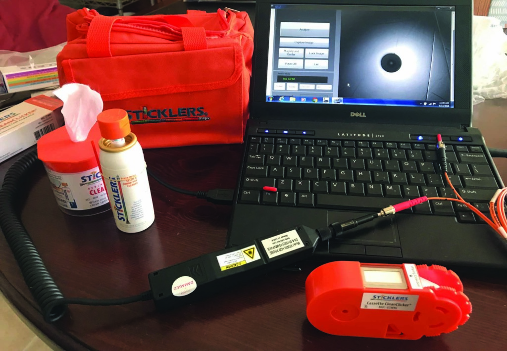
A cleaning kit will quickly remove dirt and contamination, and a video microscope can inspect connectors for dirt or damage.
If the electronics are the problem or are suspected, swap modules for spares. If that solves the problem, make sure to send that bad module out for repair ASAP.
If it’s not the electronics, start looking at the cable plant, beginning with the patchcords. They can be tested with an inexpensive visual fault locator (VFL) to confirm they have not been broken or connected wrong. A connector inspection microscope and cleaning kit are a good investment too, since the majority of fiber optic problems are due to dirty connectors. That’s another reason not to let unqualified personnel touch the fibers.
Diagnosing cable problems is a matter of shooting several spare fibers in the cable with an optical time-domain reflectometer (OTDR) and analyzing the traces. Is the cable the expected length? If it’s shorter or it has a high loss event at an unexpected point, it may indicate a damaged cable. Don’t trust the results of just one fiber. Test a few and see what they all look like. If they are all the same, you may have a cable break. If only some fibers show the problem, you may have cable damage in only a few fibers, indicating a problem with a kinked but not totally broken cable or problems at a splice point.
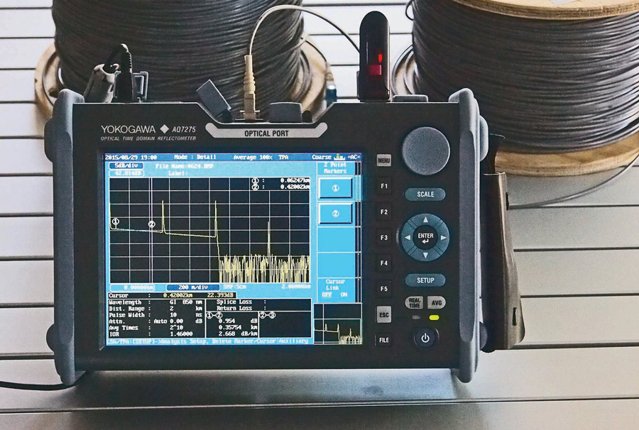
An OTDR with long launch and receive cables will help diagnose problems in the cable plant.
Remember, the OTDR is not 100% accurate. It measures fiber length, not cable length, and the cable length is approximately 1–2% shorter. Compare the length on the OTDR with data from installation testing and correlate with splice points to reduce location uncertainty. Alternatively, shoot from both ends to locate a break and average distances.
Make certain you are testing the correct cable. Using OTDR testing, one crew thought they had a break in a 6 km underground cable at 4 km. But physical inspection, including digging at the location indicated by the OTDR, showed no problem. In fact, they were testing the wrong cable. They were testing a cable 4km long running in the opposite direction from the patch panel, not the cable they thought they were testing. Their patch panel marking and documentation didn’t match.
This is where documentation helps. Having information on the length of the cable and the location of splice points — especially geographic information system (GIS) data — makes pinpointing problems easier. Comparing traces of problem fibers allows correlation of the problem location to the location of a splice closure or a service loop in a vault.
Splice closures can be the problem. Fibers can get cracked or broken in splice trays, yet not fail for a long time, perhaps after seasons of temperature changes. Splice closures can be improperly sealed, and moisture — or ice in winter — will cause damage. There are even tales of animals such as squirrels or woodpeckers attacking splice closures or cables and causing damage.
Finding a fiber break in a splice tray can be difficult. If you are close enough to use a visual fault locator (VFL), it will pinpoint the break. If the distance to the nearest fiber end is more than 4-5km, a gadget called a fiber identifier may be used.
A visual fault locator (VLF) is extremely useful at finding breaks in splice trays, couplers, etc.
Sometimes a visual inspection of a cable route will find the cause of the break faster than testing fibers. One tech remembers that a construction team was installing road signs nearby when their network went down, so he hopped in his truck and drove to the job site. There he found the construction crew stuffing the broken fiber optic cable back into the hole they had dug with an auger.
Another network went down when a helicopter flew into an optical power ground wire (OPGW) on a tower. That one was easy to find, but hard to fix, but one of our FOA instructors spliced it from a precarious perch in a bucket truck.
And always remember to ask around the offices to see if someone has been working on the network.
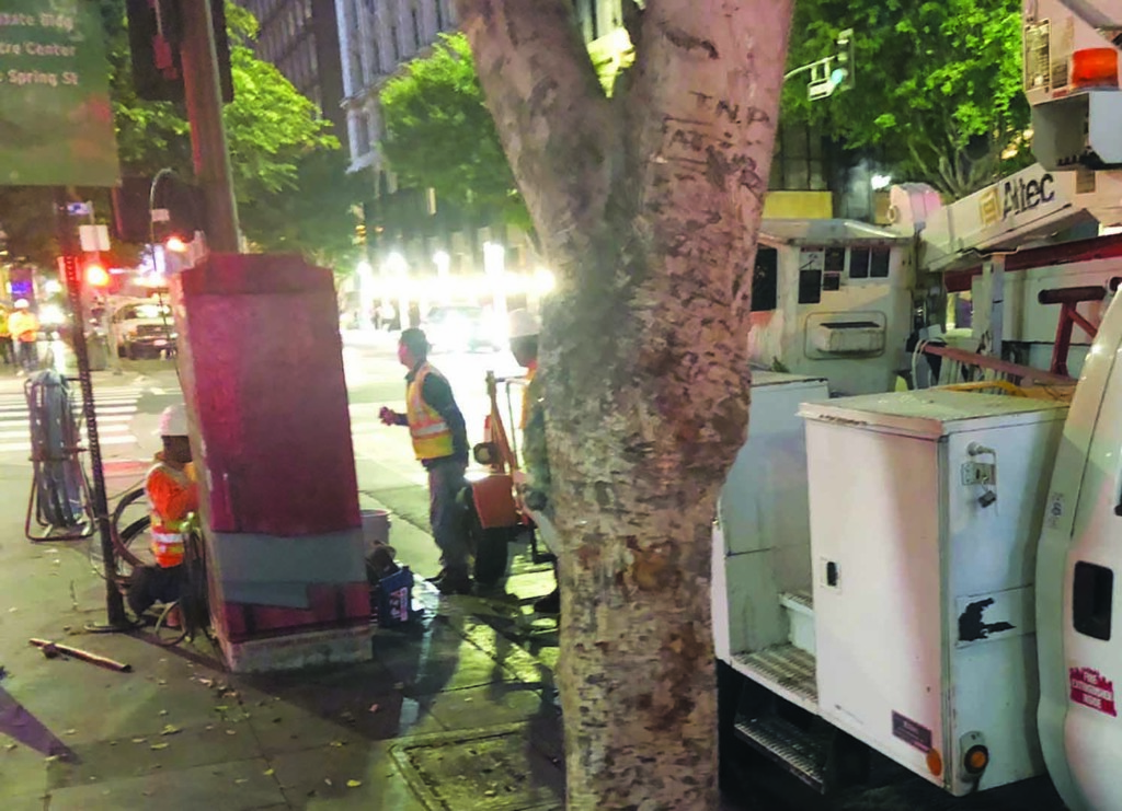
Restoration can be in a muddy field along a rural road or in the middle of a busy street in downtown Los Angeles.
Repair Strategy
Okay, there is a break. How do you fix it? You should have a restoration plan and a restoration kit complete with up-to-date documentation, a list of test and repair equipment — including where to find them — and components set aside for repair. A contact list of knowledgeable people on staff or a contractor on call is also necessary.
Many companies use contractors to install fiber optic cabling because they do not have qualified employees to do the work, or at least not enough with the experience and equipment to do the job. Lacking staff capable of diagnosing problems and making temporary repairs can be problematic, since even a contractor on call 24/7 will take time to respond.
It’s much better to have several employees trained in basic fiber optics who can maintain the network and do basic repairs. For the cost of a few minutes of downtime on a typical communications link, send a couple of techs to an FOA-approved training course and equip them with a basic OTDR, an inexpensive portable fusion splicer, and some basic tools that will allow them to at least patch up the network and get it running before the final repairs are completed.
Everyone knows techs need training, but FOA also recommends that a couple of supervisors attend a training course in person or online. Our experience is that managers who understand basic fiber optics are better equipped to oversee construction, operation, and restoration.
Once the trouble spot has been located, you will want to get the network back up as fast as possible. If it’s a break, you probably will not be able to pull the cable ends out and splice them together again unless you are near some service loops. If you can’t get enough cable to splice (you need a minimum of ~10 m or 30 feet on both ends being spliced), you will have to bring out that extra cable you saved from the installation and splice a length of that to the two broken ends.
Yes, that means you need two splices to make the repair. And you will need two splice closures and about 100 m of cable just to have enough working length. Temporary fixes are OK. Splice together enough fibers to get the network back operational, even forgoing fitting splices into closures, and come back later and carefully splice all the fibers, neatly place the splices in a closure, and replace the cable in its original location.
If you read older documents on restoration, they may suggest temporary repairs using mechanical splices instead of fusion splices. That can work, but was advice from an era when fusion splicers were rare and expensive machines. Today, a simple portable fusion splicer can be purchased for little more than the kit to make a mechanical splice. In our experience teaching techs, a fusion splicer is easier to learn how to use properly.
OTDRs are also now affordable, so there is little excuse for a network operator not to have one. However, they do need some training to operate properly. Most are touted as having automatic testing modes that do the work for the tech operating them. That may work well on testing dozens of identical fibers during installation, but doesn’t hold for troubleshooting. For that, training is required.
Post-Restoration
Once the restoration is complete, it is important to prepare for the next time a problem arises, including updating documentation and replenishing supplies. The documentation should be updated to reflect changes in the cable plant after repair. This includes any new components, new splices or splice closures, or especially any fibers that are no longer serviceable. New test data (loss measurements and OTDR traces) should be recorded and preferably compared to pre-restoration data.
Leftover Inventories of restoration supplies that are reusable should be updated. Required supplies should be noted and ordered promptly. Remember to update inventories when supplies are received. You never know when you’ll need them.
(Editor’s note: FOA’s Fiber U offers free online courses for technicians and managers.)
References
Lochbaum, Dave. “Nuclear Plant Accidents: Browns Ferry Fire,” Disaster by Design/Safety by Intent #41, July 19, 2016. Available at https://allthingsnuclear.org/dlochbaum/nuclear-plant-accidents-browns-ferry-fire.
 Jim Hayes is an author and trainer and President of the Fiber Optic Association. Find him at www.jimhayes.com.