
Line differential protection is one of the most popular applications used for transmission line protection. Line differential protection works on the theory of Kirchhoff’s current law, where the magnitude of the current flowing into the line should be equal to the current flowing out of the line. For line differential protection, the zone of protection is defined by the location of current transformers (CTs) monitoring the currents on either end of the transmission line. It is crucial for the protective relays on both ends of the line to communicate with each other when a fault condition is established and issue a trip signal for the in-zone fault.
In Figure 1, a single-line diagram shows the set-up of line current differential relays (87L) installed on either end of the transmission line. The relays monitor current from the CTs they are connected to on the either end of the transmission line. These relays, which are referred to as local relay and remote relay, are connected to each other by means of optical fiber cables for the purpose of communication. When a fault occurs on the line, the relays see the fault at the same time. Based on the information received from the other end, the relays decide what needs to be done: trip or restrain.
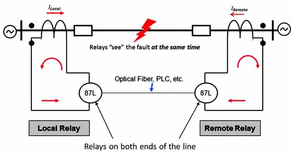
Figure 1: Line Differential Protection Implementation
Relay manufacturers use different methods to measure and compare currents in differential protection relays, including magnitude comparison, phasor comparison, phase comparison, charge comparison, or various combinations of these options. One popular method is to use the alpha plane characteristic to determine line differential condition. This article discusses line differential protection, the importance of end-to-end testing, and the procedure to test alpha plane characteristics using an end-to-end test method. Specifically, the 87L element is discussed with respect to pick-up accuracy, time of operation, dependability by simulating internal faults, and security by simulating external faults.
Understanding Alpha Plane Characteristics
The ratio of phase currents (or sequence currents) entering or leaving a transmission line is geometrically represented on a complex plane, which constitutes the alpha plane characteristics. Currents considered for the ratio calculation can be either monitored values of phase currents at remote and local relays or derived currents from calculations involving equations that use real and imaginary parts of differential and restrain currents obtained from monitored phase currents. Usage of these algorithms varies by relay models. In Figure 2, k represents the ratio of the currents.
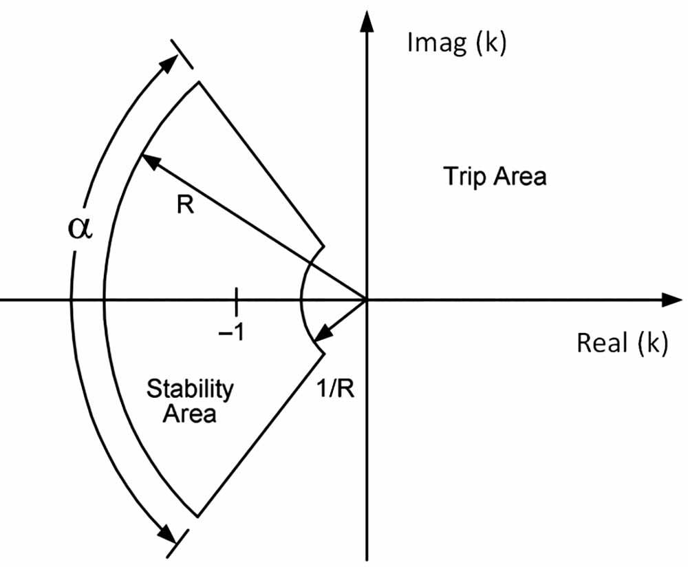
Figure 2: Alpha Plane Characteristics
The area of stability and trip can be determined by the characteristic parameters due to which any percentage differential characteristics can be mapped onto the alpha plane. The restrain region is defined by parameters such as the radius of the greater arc (R), radius of the inner arc (1/R), and the angle (α). The radius of the greater arc and inner arc determines the radius of the restrain region (stability area), and the angle (α) represents the angular extent of the restrain region. Each phase has its own alpha plane characteristics. In the example, if the A phase current monitored by the local relay is 3∠0°, then the remote relay will record 3∠180°. The ratio of the remote current to local current would be:
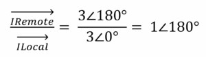
On the alpha plane, this ratio will plot on the real axis to the left of the imaginary axis. As could be seen in Figure 2, this falls in the restrain region, which is also the stability area. This case can be related to nominal load condition or an external fault depending on the current levels. In the case of an internal fault, the currents read by both the relays for their respective phases tend to be in phase with each other as they monitor the currents feeding the internal fault. This will plot the resultant of the ratio to be 0°, which falls in the trip region of the alpha plane characteristics shown above.
Significance of End-To-End Testing
End-to-end testing is the evaluation of a relay protection scheme by simulating fault conditions simultaneously at each end of the transmission line. The ability to synchronize the test systems on each end is paramount. This means that test quantities should be injected to all the relay terminals simultaneously. Line differential relays receive a set of currents from their own terminals and data of currents from the remote relay by means of various communication modes. Since the relays send time-stamped information packets to each other, even a slight slip-up of the time during injection can incorrectly stamp the packets reaching the local and remote relays, which can cause incorrect or unintended operation. Hence, a time signal from a global positioning system (GPS) clock is used to synchronize multiple test systems. Time signals are available in various standards such as IRIG-B, pulse per second (1 PPS), precision time protocol (PTP), etc. In this article, the IRIG-B time sync standard is considered for testing.
The end-to-end testing method requires multiple relay test equipment with the ability to decode the IRIG-B signal to trigger injection of analog signals simultaneously (Figure 3). The IRIG-B signal that is obtained by a GPS receiver via antenna is also provided to the relays under test. This kind of testing is used to evaluate a new protection scheme during commissioning of a substation, troubleshoot malfunction of relays, verify the relay setting changes, and other functions. Equipment (hardware/software/accessories) required to perform an end-to-end test includes:
- Two sets of relay test equipment with ability to decode IRIG-B signal and generate currents with magnitude and phase angle as specified in the test plan
- GPS receivers
- Co-axial cables (to connect GPS receiver and relay test sets and relays)
- Two computers (to drive the relay test sets at respective substations)
- Communication medium between the test technicians, i.e., cell phones or other voice communication equipment
- Test software with pre-built test plans to simulate faults in the protected zone and out of the zone (through faults) for single-phase, phase-to-phase, and three-phase faults, as well as positive-, negative-, and zero-sequence currents.
When implemented correctly, communication-based protection schemes result in efficient and reliable protection of transmission lines as compared to numerous relays that cannot communicate with each other. It is simpler to test individual relays in a scheme; however, it’s more effective to test an entire scheme as a whole, which validates not only the components, but also the communication aspect of the scheme. Issues that occur with communication-based schemes can be detected by end-to-end testing.
Test Procedure
A test set-up can be arranged to simulate a system similar to the one shown in Figure 3. IRIG-B signals must be provided to the appropriate inputs of the relay test equipment as well as the relays under test. Necessary test connections to inject analog signals to the relays must be made on both ends. Spare output contacts on both the relays should be programmed for the 87L element. A phase differential pick-up test, radius check tests, angular extent boundary tests, and timing test for an internal fault are performed. In this article, the algorithm in the relay used for testing considers derived currents from calculations involving equations that use real and imaginary parts of differential and restrain currents obtained from monitored phase currents.
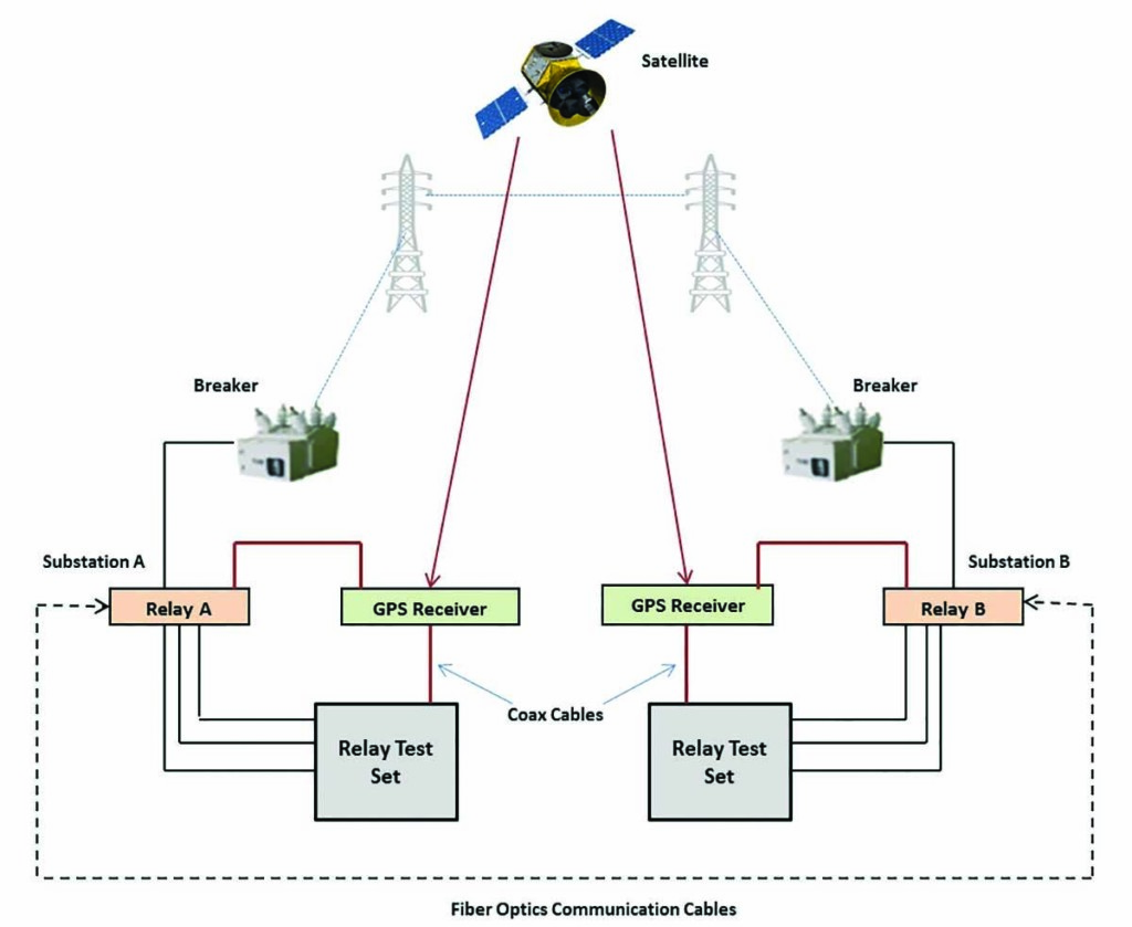
Figure 3: End-to-End Testing: The Whole Picture
Relay Settings
- Phase differential element pick-up — 0.72 pu
- Phase differential element radius (R) — 6
- Phase differential element block angle (α) — 195°
Phase Differential Pick-Up Test
The phase differential pick-up test validates the 87L logic and pick-up setting when the injected current is above the pick-up setting. This test can be performed on each phase at each end separately and does not need time synchronization. Based on the relay setting of 0.72 pu and the nominal current of 5A, the calculated pick-up value in amps is 3.6A. Therefore, the 87L element should pick up at 3.6A.
Radius Check Test
The radius check test is performed to validate the boundary of the restrain region in the alpha plane with respect to the radius from origin. Initially, the test should be conducted to verify the radius setting pick-up of inner arc of the restrain region. The distance from the origin to the inner arc of the restrain region is defined by 1/R as was depicted in Figure 2. Based on the relay settings, 1/R = 1/6 = 0.16. Once the test sets are synched during pre-fault, the test values should be varied during the fault state. The end test value at which the 87L element trips should be 0.80∠0° amps. This result value translates to 0.16 pu distance from the origin to the inner arc.
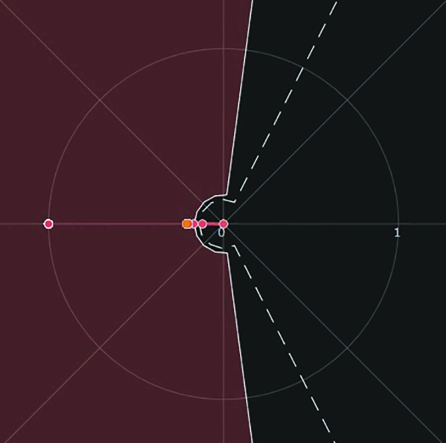
Figure 4: Alpha Plane Characteristic Plot — Inner Arc Radius Test
In Figure 4, the alpha plane characteristic shows changes in complex ratio plot based on the varied test value of currents to validate the 1/R setting. Table 1 lists the phase A currents to be injected to local and remote relays during pre-fault and fault states. Based on the currents injected to relays, the relays perform mathematical calculations using differential and restrained equations to calculate derived currents, and the ratio of those derived currents are plotted on alpha plane to define the 87L element operation.
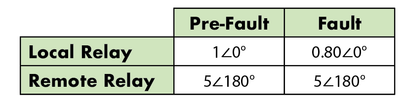
Table 1: Inner Arc Radius Test
After validating the 1/R setting, the next test will verify the radius setting of the outer arc of the restrain region. This radius setting was depicted in Figure 2 as R. To test the R setting, same pre-fault values should be injected as before. However, the fault state currents on the local relay should be varied up to 30 amps, which translates to 6 pu. This is the radius of the restrain region. As soon as the current is increased more than 30A, the complex ratio on alpha plane crosses the restrain region and trips the relay. The test procedure described above is for A phase. The same procedure can be followed to perform tests for B and C phases.
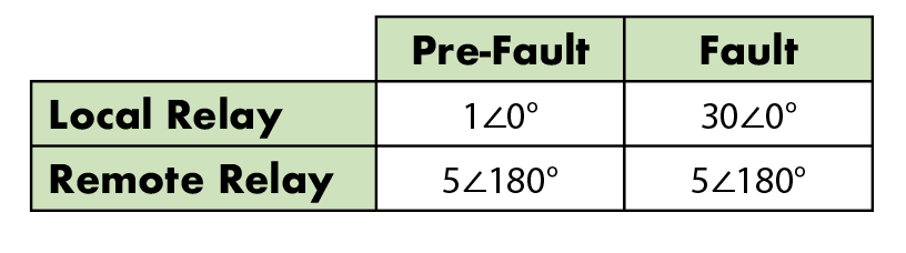
Table 2: Outer Arc Radius Test
Angular Extent Boundary Check Test
This test is performed to validate the angular extent of the restrain region on the alpha plane. The angular extent setting α was depicted in Figure 2. The α setting of the relay is 195°. Therefore, a pre-fault current injection with phase angles ∠0° on local relay and ∠180° on remote relay should be done. In the fault state, the angle of the analog currents to the local relay should be varied up in the counterclockwise direction. The relay should trip for a 98° phase angle value.
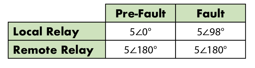
Table 3: Angular Extent Boundary Check Test 1
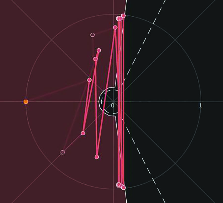
Figure 5: Alpha Plane Characteristic Plot — Angular Extent Boundary Check Test
In Figure 5, the alpha plane characteristics show changes in complex ratio plot based on the phase angle variation to validate the angular extent of restrain region. Similarly, the next test should be performed to validate the angular extent in the opposite direction from origin. The phase angle in fault state should be varied in clockwise direction for the local relay. The relays should trip at a value of –98°. The difference of angular extents between the first and second test is 98° – (–98°) = 196°. This result translates close to the angular extent setting of the relay (195°). The test procedure described above is for A phase. The same procedure can be followed to perform tests for B and C phases.
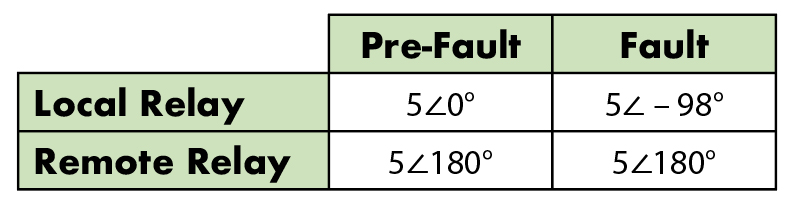
Table 4: Angular Extent Boundary Check Test 2
Timing Test for Internal Fault
An internal fault can be simulated to perform the timing test of the 87L element. Pre-fault and fault states should be set up with the values shown in the test table below. Ideally, the local relay and remote relays should trip close to a cycle as soon as the relays see an internal fault. In Figure 6, the alpha plane characteristic shows the path of complex ratio plot transitioning from restrain region to operate region based on current injection switch from pre-fault to fault state.
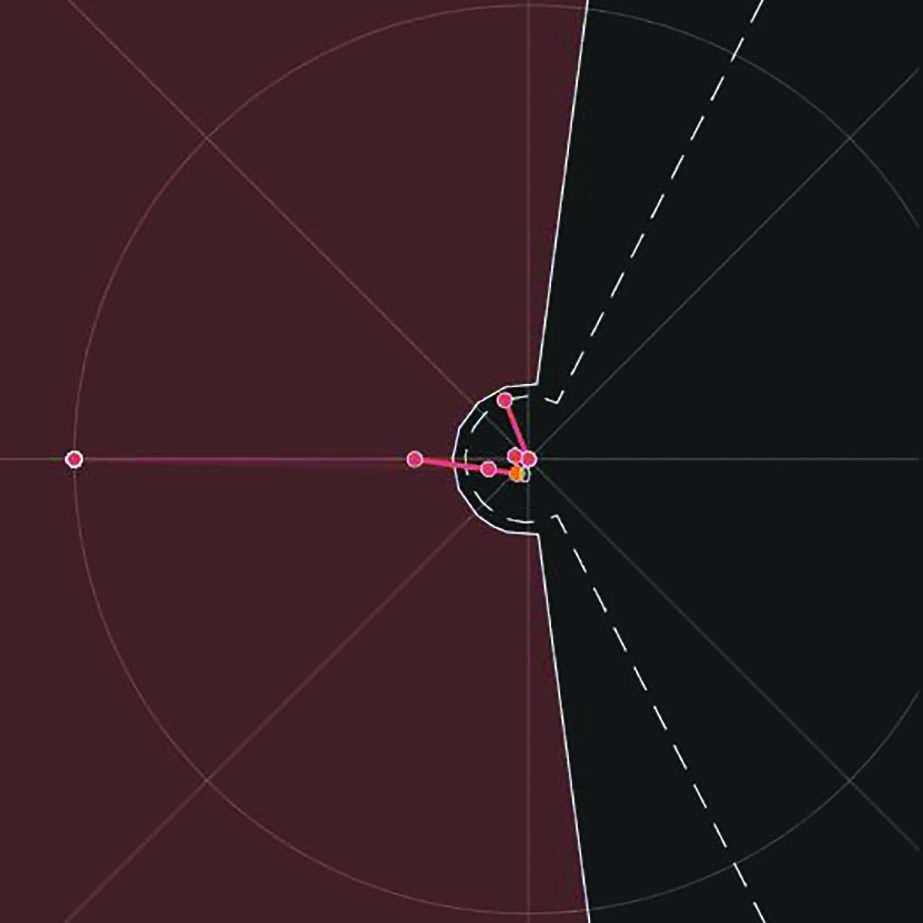
Figure 6: Alpha Plane Characteristic Plot — Internal Fault Timing Test
A similar set-up of pre-fault and fault states can be set up to simulate external fault currents. The relays should restrain from tripping, as the complex ratio of currents plots on to the restrain region on the alpha plane.
Relays may also have settings enabled for 87L negative sequence and 87L zero sequence elements to provide protection for single line to ground faults and unbalanced fault conditions. The tests discussed for phase element in this article should also be performed to validate negative sequence and zero sequence elements.
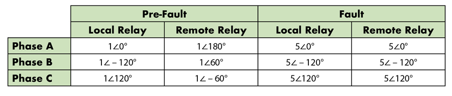
Table 5: Timing Test — Internal Fault
Conclusion
Line differential protection has been implemented all over the world by the vast majority of utilities. It is significant to validate the protection scheme for its accurate operation for faults. End-to-end testing validates the entire communication-based protection scheme including the operation of the relays as well as the communication between the relays. Knowledge of end-to-end test methods and field experience helps technicians perform the testing more efficiently. This article provides insight on testing line differential protection using the end-to-end test method and its importance, as well as testing of alpha plane characteristics to validate the line differential element through the pick-up test, radius check test, and angular extent check test.
References
James Ariza, G Ibarra. “Application Case of the End-to-End Relay Testing using GPS-Synchronized Secondary Injection in Communication Based Protection Schemes.” Available at: http://www.netaworld.org/sites/default/files/public/neta-journals/NWwtr06Megger.pdf.
Schweitzer Engineering Laboratories. “SEL 411L Advanced Line Differential Protection, Automation, and Control System instruction Manual,” May 10, 2019. Available at
www.selinc.com.
G. Benmouyal. “The Trajectories of Line Current Differential Faults in the Alpha Plane.” Line Current Differential Protection: A Collection of Technical Papers Representing Modern Solutions, 2014.
Chris Werstiuk. “End-to-End Testing,” Valence Electrical Training Services, 2010.
Abel Gonzalez. “Advanced End-to-End Testing Webinar.” Available at https://register.gotowebinar.com/recording/3052100615461400833.
 Sughosh Kuber is a Relay and Protection Applications Engineer at Megger North America, where he provides technical support to service companies and utilities responsible for reliable operation of electrical networks. Sughosh brings over 9 years of field experience and academic research in power systems from protection schemes and testing to data analysis for energy efficiency and sustainability. Sughosh received his MS in electrical engineering from New Mexico State University.