
Ethernet is considered a fast, reliable, and scalable local area network (LAN) technology that has become predominant within electrical utility substations. Unlike information technology (IT) LANs, which are used to move general non-critical information, operational technology (OT) LANs carry information that is used to directly perform critical control functions such as tripping, blocking, and interlocks.
To ensure that electrical utility substation OT LANs meet the performance requirements of critical applications, careful consideration must be given to every aspect of design and implementation from topology, media, and switch selection through to the configuration of primary and failover paths.
This article explains the IEC 61850 communications services supported within the digital substation and progresses on to key aspects of the design, testing, and commissioning of the digital substation OT LAN. Cybersecurity is a very important consideration but is beyond the scope of this article.
DIGITAL SUBSTATION ARCHITECTURE AND IEC 61850
Figure 1 illustrates digital substation architecture and IEC 61850 communication services. Within the digital substation, intelligent electronic devices (IEDs) are connected to the local human-machine interface (HMI), routers/gateways, and engineering PCs on the station bus Ethernet LAN. The IEDs are also connected to the switchgear and merging units on a second communications bus known as the process bus.
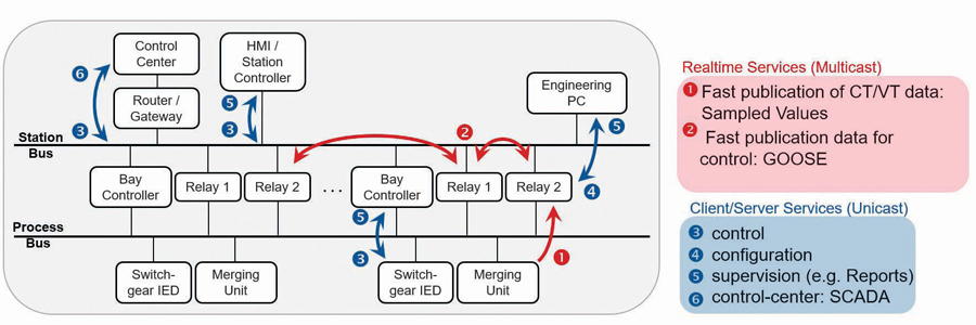
IEC 61850 provides two low-latency or real-time communications services:
- Generic object-oriented substation event messaging (GOOSE), which is intended to replace the hard wiring of signals between IEDs
- Sampled values (SV) streams digitized currents and voltage quantities from merging units, which protective relay IEDs use as inputs to their protective elements.
TWISTED PAIR ETHERNET MEDIA
Let’s start by discussing the communications media used within digital substations. Twisted pair copper and fiber optic Ethernet cables are the most common media within the substation. The twisted pair cables should have a minimal rating of Cat5e, which is a rating of the cable speed based on physical parameters such as shielding, twists per inch, and length. Today, Cat6 has superior performance to Cat5e and is now typically easier to source here in North America than Cat5e, making it a suitable and superior alternative to Cat5e. The maximum cable length should be no more than 100 meters. Beyond this length, the signal begins to degrade, reducing the speed and reliability of the connection. Twisted pair copper Ethernet cables are made from four twisted pairs of conductors terminated in an eight-pin RJ45 connector. The wiring standards for the terminations are T568A and T568B (Figure 2).
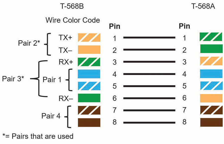
The difference between the two standards is the pin assignment for the orange and green pairs. Cables with T568A wiring on one end and T568B on the other are known as crossover cables. You can identify a crossover cable by comparing the order of the wire color on each end.
- If the wire colors are in the same order on each end (regardless of which pin configuration is used), it is a straight-through cable meant to connect data terminal equipment such as an IED to data communications equipment such as an ethernet switch.
- If the wire colors are in a different order at each end, the cable is a crossover cable meant to connect two data communications or data terminal pieces of equipment together.
Today, most Ethernet switches, IEDs, and routers support automatic medium-dependent interface crossover (auto-MDIX), which can detect which type of port or cable is connected and automatically swap the transmit and receive pins, accordingly, removing the need for crossover wiring. Given that most modern devices support auto-MDIX, it is still best practice to use a crossover cable to connect interposing switches and connect the drop ports of the switch to the IEDs using a straight-through cable. Twisted pair Ethernet media is typically used within the electrical substation for the connection of HMIs and engineering laptops to the LAN, but the lack of isolation and limited electrical noise immunity does not lend twisted-pair copper Ethernet cable media well to other applications within the substation.
FIBER OPTIC ETHERNET MEDIA
The second and most common communication medium within modern substations is fiber optic cable. Two types of fiber optic cable are used within substations: single-mode fiber and multimode fiber. Several wavelengths of light are used as shown in Table 1.
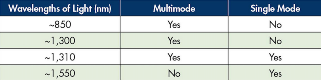
Table 1: Light Wavelength in Fiber Optic Cables
These light wavelengths have very low attenuation as they propagate through fiber media, and transceivers can be manufactured that will operate efficiently at these wavelengths of light. It is very important to note that unlike copper wire ports, fiber optic ports have fixed baud rates, so the transceivers of the two devices must be at the same baud rate and use the same wavelength of light for transceivers to be able to see each other to communicate.
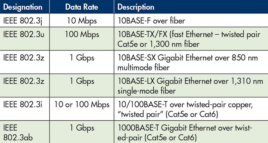
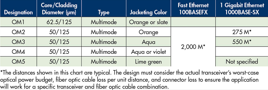
Table 2 provides the designation for several commonly used fiber optic Ethernet port configurations. The designer should ensure that the fiber cable is compatible with the ports and that the ports of connected devices are compatible (have the same designation).
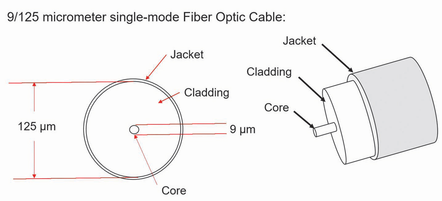
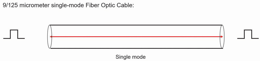
Single-mode fiber (Figure 3 and Figure 4) is ideal for runs of hundreds of kilometers, but the small core diameter is very sensitive to contaminants and requires strict adherence to cleaning and handling to ensure reliable operation.
Multimode fiber optic cable has several advantages over single-mode fiber that have allowed it to become the dominant media within the modern substation. Multimode transceivers are available at a lower cost than signal mode transceivers, and multimode fiber optic cable has a much larger core, hence more tolerance to dirt and contaminants than single-mode fiber core.
It is still important to follow correct handling and cleaning procedures with multimode fiber components. The larger core of multimode fiber (Figure 5) does not come without a cost.
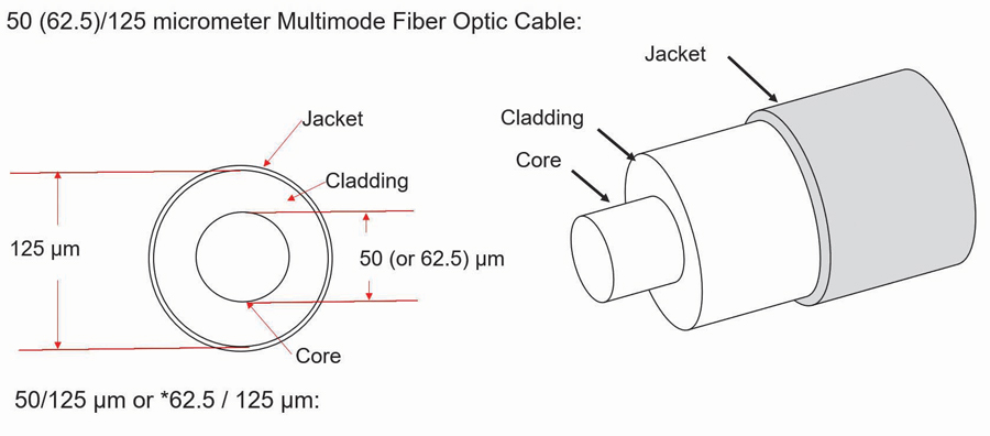
As the photons of light traverse the fiber, some photons take a longer path than others (Figure 6). Therefore, the pulses of light making up the data transmission tend to round and increase in width the farther they traverse the fiber. This is called dispersion.
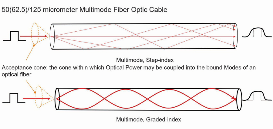
Ethernet has very strict timing and as the baud rate increases, this timing becomes more and more critical. Dispersion is the primary factor that limits the maximum length of multimode cable to typically 2 km for 100 Mbps. This drops very quickly to only several hundred meters for speeds of 1 Gbps. Table 3 shows the rated maximum distance of several types of multimode fiber depending on the baud rate.
Single-mode fiber optic cable does experience chromatic and polarization mode dispersion.
- Chromatic dispersion occurs when the transmitting light source is not of one wavelength, and the transmission of different wavelengths of light is at different speeds within the fiber.
- Polarization mode dispersion is a phenomenon of light traveling in a medium as a wave with components at right angles.
Some materials, like glass optical fiber, have a different index of refraction for each of those components of the light wave; this is called birefringence. A different index of refraction means light travels at a different speed. Having said this, the dispersion of single-mode fiber is of no concern when we consider what the required length of single-mode fiber within the footprint of a typical substation would be.
The second factor limiting the length of single as well as multimode cables is the attenuation of the light as it traverses the fiber. The maximum cable length of the fibreoptic transceivers specified by the switch vendor does not consider the connector and splice losses of the fiber run. The amount of fiber optic cable plant loss that a datalink can tolerate while still operating correctly is called the optical power budget. Think of the optical power budget as the difference between the output power of the transmitter and the input power requirements of the receiver, both of which are defined as power coupled into or out of an optical fiber.
In some cases, the optical power budget has minimum and maximum values. This means a minimum value of loss is needed to prevent the transmit optical power from overloading the receiver, and a maximum value of loss is needed to ensure the receiver has sufficient signal to operate properly. The loss budget is a calculation of the estimated loss a cable plant will have. This end-to-end, estimated total loss calculation is based on the estimated cumulative losses of the components used in the cable plant including the fiber, connectors, and splices.
During the design phase, the loss budget is used to ensure the cabling being designed will work. After installation, the calculated loss budget is compared to the actual measured loss to verify that the cable plant was installed correctly. This topic has much more depth than this very abbreviated summary. To provide further clarity, we will work through a typical multimode fiber optic cable run within a substation (Figure 7).

This is the longest cable run for the application. This run also has the maximum number of connectors of any run within the cable plant. In this example, there is no minimum loss as the transmit optical power is not strong enough to overload the receiver, which is typically the case for multimode ports. The transmitter has a minimum optical power rating of -20 dB and the receiver has a maximum receive sensitivity of -28 dB.
- Cable loss = 3 dB/1,000 meters for this specific example. Check your cable specifications for the loss per km.
- Optical power budget (OPB) = Tx min(dB) – Rx(max) = 8 dB. The switch manufacturer typically provides this specification.
- Worst case OPB (WOPB) = OPB – 1 dB = 7 dB. This is normally only applicable to single-mode applications but it does not hurt to be conservative.
- System gain equals cable loss plus connector loss where:
- Cable loss = cable length x attenuation per unit length (dB).
- Connector loss = number of connector pairs x 0.5 dB (0.3 to 0.5 typical). Note that the TIA/EIA standard calls for 0.75 dB per connector, but for modern connectors, 0.3 dB to 0.5 dB have typically been found to be more accurate.
- System gain = 250 meters x -3 dB/1,000 meters + 4x – 0.5 dB
- = -2.75 dB
- Operating margin = WOPB + system gain = 7 dB – 2.75 dB = 4.25 dB
From this example, we can see that the operating margin (the difference between the system gain and the WOPB) is 4.25 dB. A rule of thumb is that the ideal operating margin should be 3 dB or greater for multimode applications to ensure reliable operation. Given that this is the longest multimode fiber link for this substation, the designer can be assured that the multimode cable plant will provide a reliable link between all devices if properly installed.
TESTING
There are many aspects of fiber optic links testing, and electrical utilities typically have access to installers that have the knowledge and equipment to test the cable plant. One of the simplest tests is the length loss test. In this test, a light source of the same wavelength as that of the application is connected by a 1-meter cable to a receiver. The source output is adjusted such that the receiver measures the signal as 0 dB. The light source is then connected to one end of the run and the receiver is connected to the other end. The attenuation measured by the receiver indicates the actual attenuation of the link, which should be close to what you calculated using the procedure in the preceding paragraph.
Adding patch panels is a great way to manage fiberoptic cable runs. Devices terminate at a local patch panel and longer fiber runs are used for the interconnection between the patch panels. The only drawback to patch panels is the introduction of additional connectors, which introduces additional loss.
Selecting the Right Ethernet Managed Switch
The Ethernet switch is like a data manifold that in combination with Ethernet cables forms the LAN that provides the Ethernet communication connectivity between the IEDs, merging units, HMIs, gateways, routers, and PCs within the substation. Many manufacturers supply utility-grade managed switches that support numerous different features and physical form factors.
Many factors must be considered when choosing a managed switch for OT applications. In fact, there is enough to consider when selecting a managed switch for OT LANs to warrant an article on that topic alone. It is strongly recommended to go through a selection process when choosing the ideal OT-managed switch for your application, as not all claimed utility-grade managed switches are equal.
Following is a list of features that are strongly suggested to be considered during the evaluation process. The list is modest and so you may find it surprising that many utility-grade managed switches do not support all of these features, and compromises must therefore be made.
- Designed to meet IEEE 1613 Class 2 and IEC 61850-3.
- Supports an option for dual power supplies (AC and DC) that are hot-swappable.
- All switch configurations are accomplished through a web interface to allow personnel to become proficient in a relatively short period of time.
- Default IP address, administrator account name, and password to allow easy initial access.
- Supports real-time day clock and calendar.
- Supports SNTP client/server.
- Supports IEEE 1588 transparent clock.
- Supports switch local diagnostic log.
- Supports Syslog to three agents.
- Supports IEC 61850 data model, MMS server, and report functionality (for SCADA/testing).
- Supports multiple user accounts with at least three levels of users:
- Administrator account can create user accounts.
- Multiple engineer accounts can configure all features of the switch, excluding creating or deleting user accounts.
- At least one operator account can look at the switch configuration/ operating menus but cannot make any changes.
- Supports twisted pair and fiber optic ports at port speeds of 100 Mbps with uplink ports (switch-to-switch connection) at 1 Gbps.
- Supports several hundred concurrent port-based VLANs. An x/y port-based VLAN configuration matrix is ideal (the x-axis being the port and the y-axis being the assignment of VLANs or vice versa)
Syslog
Syslog is a standardized way for networking equipment such as managed switches to send events to a central computer running a syslog agent. For example, if a device connects or disconnects from a switch port, the switch will send a message to the Syslog agent indicating that the status of a specific port has changed along with a time stamp. In this way, the status of all switch ports, in addition to major and minor events on the LAN, can be monitored at the Syslog agent with very little configuration effort (Figure 8).
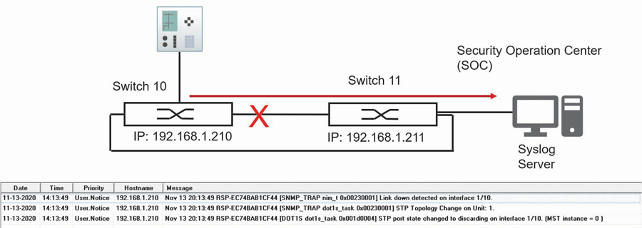
Syslog is an extremely powerful troubleshooting tool for the OT LAN. Some switches have an IEC 61850 data model, and there is thought that this data model could be monitored by an IEC 61850 client to provide similar functionality to Syslog. The reality today is that the IEC 61850 data model within most managed switches is poor to nonexistent, and there is a substantial integration effort to allow the IEC 61850 client to provide rudimentary diagnostics. Syslog is universally supported by all major managed switch vendors and is an excellent diagnostic tool that should be implemented.
PATH REDUNDANCY
Redundancy is a key consideration for OT LANs. Ideally, in the event of a LAN component failure, the LAN can continue to provide acceptable performance. Many physical LAN topologies provide a redundant physical path such as a ladder topology. Ethernet frames do not have a maximum time to live, so a redundant link allows a broadcast message to be duplicated at each junction. Over a short period of time, this duplication will use up all available bandwidth of the LAN and can cause MAC table instability within the switch. This is known as a broadcast storm.
IEEE has standardized five redundancy algorithms:
- Spanning tree protocol (STP)
- Multiple spanning tree protocol (MSTP)
- High-availability seamless redundancy (HSR)
- Rapid spanning tree protocol (RSTP)
- Parallel redundancy protocol (PRP)
These algorithms allow for the provision of redundant physical paths while eliminating broadcast storms. This article examines how RSTP and PRP (the last two redundancy algorithms listed) can work together to provide redundancy as well as a mechanism to plan the primary and alternate data path between devices.
Rapid Spanning Tree Protocol
Rapid spanning tree protocol (RSTP) is the most common redundancy protocol used today within Ethernet LANs. Even a short summary of RSTP operation would take considerable space, so this article provides a very high-level description of its operation to understand how it can be used to configure normal and alternate data paths. The primary purpose of RSTP is to create a logical loop-free topology when physical redundant paths are present in the LAN. The loop-free topology or spanning tree is built based on the priority and costs of the different paths from each switch to the root switch. The links between switches can operate at different standard baud rates. Each of these baud rates is assigned a specific cost — the values of these costs are not important for this discussion.
The first step is to choose a topology of switches that allows for normal and failover paths to be easily configured using link cost. The ladder topology shown in Figure 9 is an ideal topology for this purpose.
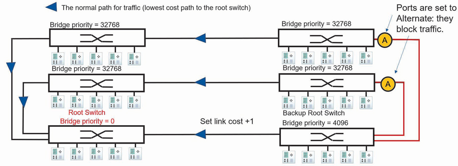
The next step is to configure a root and backup root switch by setting a parameter called bridge priority within the switch from its default of 32,768 to 0 for the root and 4,096 for the backup root. The other managed switches will use the RSTP protocol to determine the most favorable loop-free path between each managed switch and the root switch. The lowest path cost is the first parameter used in this determination.
In the example topology in Figure 9, the links between all switches are operating at the same speed, hence they are said to have the same cost except for the link between the lower two switches whose cost has been raised by 1. The active path from each switch to the root is negotiated in the following way:
- Switches with a link directly connected to the root switch will use that path as it is the lowest cost path to the root switch.
- The two switches to the right and above the backup root switch are not connected directly to the root switch and have two paths to the root: the path via the backup root switch and the path to the left.
- The path via the backup root has a cost of 1 more than the path to the left, so both switches will choose the path to the left as the normal path to the root switch (see Figure 10).
- The alternate paths via the backup root switch are logically blocked to create a loop-free topology.
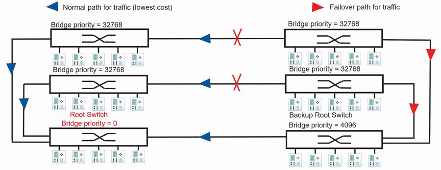
By adjusting the cost of one link, we have planned the normal and failover path between all switches and the root switch. Therefore, we now know the normal and failover data flow between connected devices. Knowing the data path or the virtual wiring of traffic between devices is required during the commissioning phase to verify connectivity of the normal and failover path and enable parameters such as message latency from one location on the LAN to another to be measured. To troubleshoot, you need to know the data path between devices.
A failure of the normal path between managed switches is detected, and the RSTP protocol running on the switches re-enables a redundant path to restore the communications path between switches (Figure 10).
Parallel Redundancy Protocol
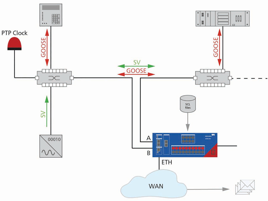
The disadvantage of using a single LAN with RSTP alone is that after a failure of a normal path, there is a short period of time when messages may not be able to get through the LAN until convergence to a new loop-free topology is complete. Parallel redundancy protocol (PRP) defined in the IEC 62439 standard provides seamless recovery and zero communication packet loss to address this issue (Figure 11).
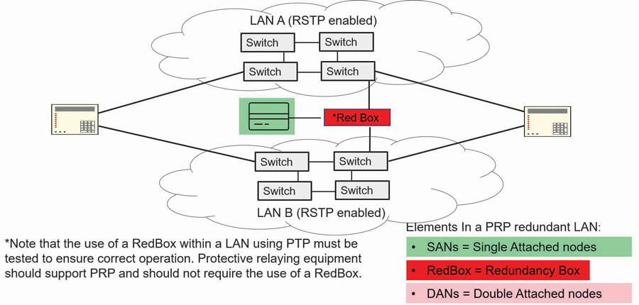
The PRP network is composed of devices with double attached nodes (DANs) and single attached nodes (SANs). Depending on the application, only the critical nodes may need a double attachment. The DANs are connected to two independent LANs operated in parallel, referred to as LAN A and LAN B. A DAN will simultaneously send out each Ethernet packet on both networks. The recipient will process the information as soon as the first copy is received at one of its ports. If both networks are operating correctly, the recipient will receive the second copy of the message on the other PRP port after a short time delay. If one of the two networks is not operating correctly, the packet will still be received through the operating network. When a destination node receives a packet, the information from the first copy is taken and processed while the information from the second copy is discarded. For demanding real-time applications like time-critical GOOSE messaging and sampled values, using PRP is recommended.
PORT-BASED VIRTUAL LANs (VLANs) AND PRIORITY
Multicast messages used for real-time data such as GOOSE and SV are treated by the switches as broadcast traffic; this means they will be sent out on all ports except the port they are received on. When traffic is received at a device port, some processing must be performed on the traffic to determine whether the traffic is for this device. Given the volume of multicast traffic, it is desirable to filter this traffic so that only the required traffic appears on the drop ports to reduce this processing to a minimum.
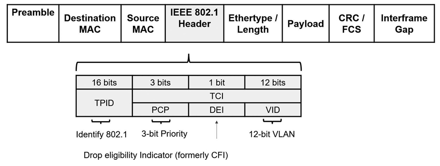
Two mechanisms can be used to filter multicast traffic: multicast filtering and VLANs. Given that the IEEE 802.1 header shown in Figure 12 supports VLANs and priority and that VLANs and priority are explicitly referenced within the IEC 61850 standards, this article explains the use of VLANs and priority to filter multicast messages.
Priority
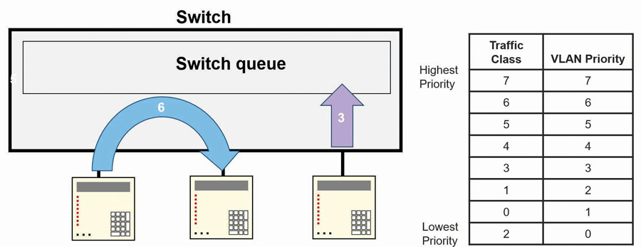
When the switch is VLAN-aware, it will look for the 802.1 header as frames ingress the switch. If two messages ingress the switch at the same time and the switch determines both must egress on the same port, the switch will forward the frame with the higher priority to egress the port, while the second frame will be buffered by the switch until the first frame is transmitted (Figure 13).
The OT LAN implementation of port-based VLANs is shown in Figure 14. The various shapes represent different multicast messages, while the arrows indicate the direction of these messages on the LAN. The number within each shape/message indicates the VLAN assigned to the message.
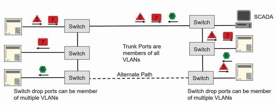
The ports that are used to connect between switches are members of all VLANs used by GOOSE and SV multicast messages within the application such that all multicast messages can propagate to all switches. The drop ports of the switch are the switch ports connected to end devices. These drop ports are configured to egress only messages that have a VLAN ID that identifies the message as one of the messages the end device should receive. In this way, only the multicast messages intended for the IED will be received. The switch filters out all but the multicast messages intended for the IED.
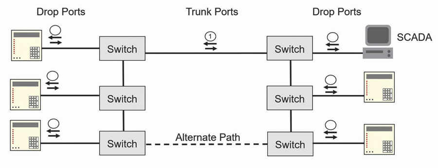
SCADA messages shown in Figure 15 are not sent with the 802.1 header, so they do not contain a VLAN ID. All messages that ingress a VLAN-aware switch must have the 802.1 header, so the switch will automatically add the 802.1 header to the SCADA message with the default VLAN ID that has been assigned to the ingress port. When a message assigned to the default VLAN of the port egresses the switch, the 802.1 header is removed from the message. By ensuring that all switches use the same default VLAN for all ports, the SCADA system will be able to communicate with all devices on the LAN as if the switches were not VLAN-aware.
OT LAN TESTING AND COMMISSIONING
Now that the LAN is built and the devices are connected, we can focus on how to commission and test the LAN. Given that each application is different, only some general guidance is provided. The managed switches should be provisioned with at least two, but ideally three, spare copper ports for commissioning and troubleshooting.
The primary tool for commissioning and troubleshooting the OT LAN is an IEC 61850 protocol analyzer with analog inputs such that GOOSE, I/O status, SV, and actual analog signals can be conveniently placed on one timing diagram to analyze faults and system performance. LAN connections should only be disturbed when performing precise timing measurements as required in the case of latency measurements. All other tests can be performed by configuring the managed switch to mirror the traffic of a specific port to one of the spare ports connected to the protocol analyzer. Switch port failures can be simulated by disabling a switch port through the switch web interface. The most common tests for a digital substation include:
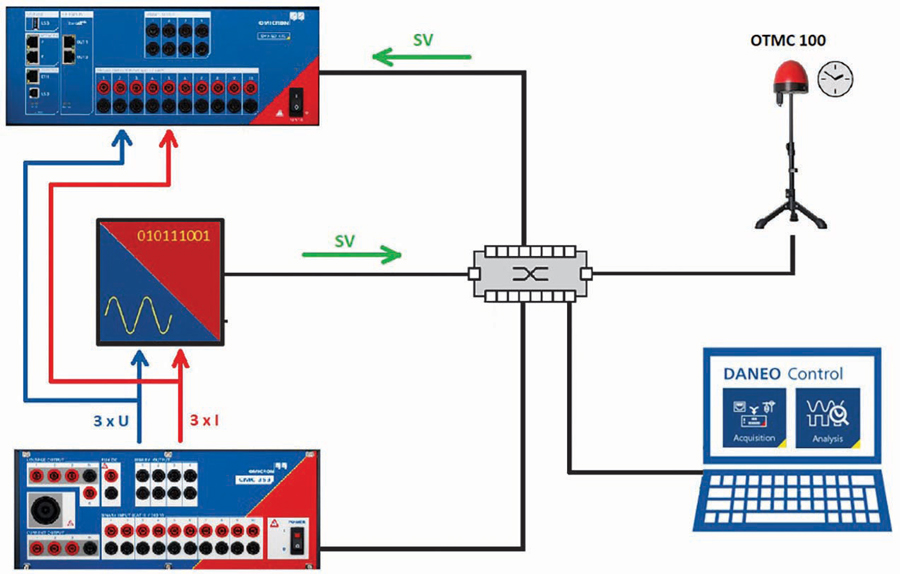
- Verifying merging unit performance (Figure 16)
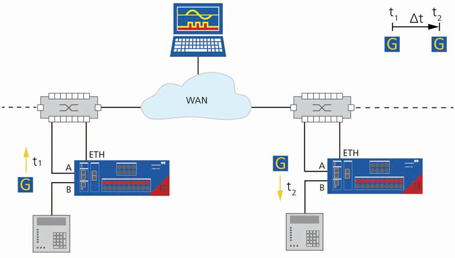
- Measuring latency (Figure 17)
- The protocol analyzer should be able to load the substation SCL files and perform automatic verification of all data flows rather than performing such tasks manually which would be error-prone given the number of parameters to check within each message (Figure 18).
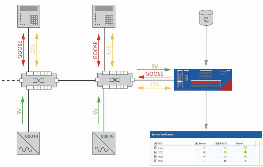
- The protocol analyzer should also be able to supervise GOOSE and/or SV messages and alarm and record when a loss of either is detected (Figure 19).
CONCLUSION
Modern digital substation protection and control solutions sit on a foundation of a well-designed OT Ethernet LAN. This article provides a very brief overview of some of the best practices for OT LAN design, commissioning, and testing. There is much more to cover, so you are encouraged to seek out courses on the design, commissioning, and testing of OT LANs to further your knowledge.

Steel McCreery joined OMICRON electronics Canada Corp. in 2020 as an Application Engineer for Power Utility Communications where he is focused on utility communications and substation cybersecurity. Steel began his career in factory automation while employed at various automation equipment manufacturers. He joined GE Multilin in 1999 to develop its international training center focused on protective relaying and substation automation. Over 14 years at GE Multilin, Steel’s role expanded into marketing and R&D before accepting an automation role at SEL focused on SEL’s communications products. Steel graduated from Humber College of Applied Arts and Sciences as an Electronics Engineering Technologist.