
Bushings are the means by which electric power passes to and from different electrical devices, as they provide a point of interface for electrical voltage to be applied and current to pass to and from an electrical apparatus. The bushing’s center conductor is above ground potential and must be electrically insulated from the tank walls, which are at ground potential. The bushing’s main function of allowing the current to pass through the apparatus cannot be achieved without the bushing’s ability to insulate the main conductor from ground.
Bushing construction includes condenser and non-condenser types. Most power transformer high-voltage bushings today are the condenser oil impregnated paper (OIP) type. These bushings have a series of dielectric layers with conductive foils between each layer to improve electric field uniformity by grading the voltage drop across the insulation. OIP-type bushings are susceptible to failure due to aging, contamination, and deterioration of the composite insulation system. Therefore, a non-intrusive and non-destructive testing technique capable of evaluating changes in the dielectric properties of the inner insulation is vital for power system operators and manufacturers of high-voltage (HV) equipment.
Bushing tests performed during maintenance include insulation tests, including power factor (PF), capacitance measurements, and dielectric frequency response (DFR); conductor and connections integrity (low-resistance measurements); infrared inspections (usually to determine the oil level of the bushings); and in specific cases, dissolved gas analysis (DGA) and partial discharge (PD) tests.
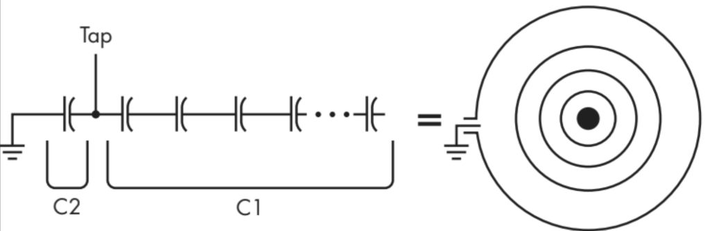
Figure 1: Modeling the OIP Bushing as a Set of Capacitive Layers
This article focuses on PF and capacitance tests and troubleshooting techniques on OIP type bushings. The PF test on bushings is susceptible to external influences that may generate false results, so before condemning a bushing, it is important to troubleshoot the result to verify its validity and provide accurate assessment. Knowing construction characteristics and testing techniques is necessary to understand the results and how to troubleshoot them. The following sections describe OIP bushing characteristics, best testing practices, and several troubleshooting techniques for PF and capacitance measurement.
OIP Bushing PF Test
OIP bushings include a capacitive divider with multiple capacitors grouped by a tap connection. The values of the two main capacitances or two capacitors C1 and C2 are usually indicated on the manufacturer’s bushing nameplate. The tap connection, depending on its constructive characteristic, is classified as a test tap or a voltage tap.
IEEE C57.19.00 states that the test tap is a connection to one of the conducting layers of a capacitance graded bushing for measurement of partial discharge, power factor, and capacitance values from conductor to tap. The voltage tap is a connection to one of the conducting layers (Figure 1) of a capacitance graded bushing providing a capacitance voltage divider. Additional equipment can be designed, connected to this tap, and calibrated to indicate the voltage applied to the bushing. This tap can also be used to measure partial discharge, power factor, and capacitance values.
Lower-voltage bushings do not require a tap, and the capacitance (C) of a bushing without a voltage or test tap is the capacitance between the high-voltage conductor and the mounting flange (ground).
C1 capacitance, the bushing’s main insulation, is measured between the high-voltage conductor and the voltage tap or the test tap. C2 capacitance is the insulation layer between the tap and mounting flange (ground); it is regularly shorted during normal operation or connected to a potential measurement device for online monitoring or as auxiliary power. If there is no tap, the PF testing is performed using the hot collar technique, described further in the article.
Power Factor Testing and Setups
PF and capacitance measurements of C1 and C2 (Figure 2) are performed sharing the same test setup: All the bushings on each side of the voltage level of the transformer should be isolated and shorted. All groups of untested bushings should be grounded.
The test is typically done at line frequency, 10 kV for C1 and 500–2000 V for C2, or at the voltage suggested by the bushing manufacturer depending on the application. Before applying a test voltage to the tap, the maximum safe test voltage must be known and observed. Only the tap cover for the bushing to be tested should be removed.
For C1 measurements, the test is conducted in the ungrounded-specimen test (UST) mode, which eliminates losses leaking to grounded portions of the bushing.
C2 measurements (Figure 3) use the grounded-specimen test with guard (GST-g) mode, which energizes the tap and measures losses leaking from the tap to ground. This measurement is not appreciably affected by connections to the bushing center conductor.
For bushings not equipped with either a test tap or a voltage tap, the main field measurement that can be performed is the hot collar test (Figure 4), which generates localized high-voltage stresses through the various sections of any bushing or pothead so the dielectric losses can be measured. This is accomplished by applying the voltage to a conductive collar band designed to fit closely to the porcelain surface, usually directly under the top petticoat. The bushing center conductor is grounded by connecting it to the red cable and using the GST-GND test mode, which measures the overall losses leaking to the center conductor and the ground.
The test measures the losses in the section directly beneath the collar and is especially effective in detecting conditions such as voids in compound-filled bushings or moisture penetration since the insulation can be subjected to a higher voltage gradient than can be obtained with normal bushing tests.
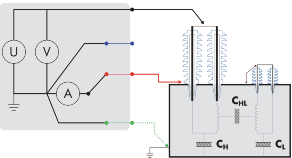
Figure 2: Setup for C1 Power Factor and Capacitance Measurement Using UST Test Mode
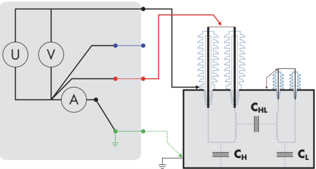
Figure 3: Setup for C2 Power Factor and Capacitance Measurement Using GST-g Test Mode
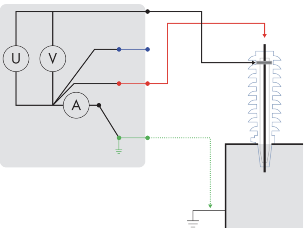
Figure 4: Setup for Hot Collar Measurement Using GST-GND Test Mode
Test Result Evaluation
Generally, power factor measurement results are evaluated by comparison with standard defined limits or trending of historic values. Such limits vary depending on the type of bushing and are defined at a specific test voltage and frequency. Table 1 shows the accepted IEEE C57.19.01 and IEC 60137 standard limits for PF values for OIP bushings. Typical values for new bushings range between 0.2% and 0.4%.
A change in PF can indicate problems such as moisture ingress, degradation, carbonized parts, or bad contacts. According to CIGRE 445, a doubling of the initial PF value warrants either more frequent monitoring or replacement.
A change in capacitance could indicate a breakdown between capacitive layers. An increase of 10% in the value of capacitance from the nameplate value could warrant replacement of the bushing.
The best way to visualize the results of insulation-related measurements is as a function of time. An increase on the value of PF or capacitance over time indicates deterioration of the insulation and should prompt further investigation or removal of the bushing depending on the depth or slope of the variation. A higher slope or deeper variation indicates acceleration of the deterioration of the insulation system and can provide an early indication of failure.
It is important to note the PF results are both frequency and temperature dependent. Test frequency is more easily controlled and depends on the test instrument and the selected test method. Temperature, on the other hand, depends on environmental factors. Trending PF values is only possible if all the results are corrected to a single reference temperature. Temperature correction factors provided by manufacturers are a popular way of dealing with this issue, but it’s proven to be average at best and may or may not match the true thermal condition of the dielectric under examination at the time of testing.
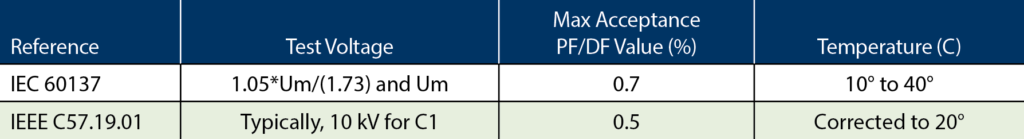
Table 1: International Standards for PF Acceptance Limits
Field Errors and Troubleshooting Techniques
Properly handling testing techniques assures correct results; however, there may be situations where the results are not as expected. In cases like this, the first suspect is the test instrument. If there is doubt about the PF test set, one common troubleshooting technique is to perform an open-air test, which is commonly described in the instrument’s user manual. An additional test to verify the instrument is to measure a reference capacitor.
Successful troubleshooting requires full understanding of the UST, GST-g, and GST-GND test modes and full command of the operation of the instrument to be able to use these modes at will.
The various conditions that can affect a PF measurement such as temperature, moisture, contamination, and handling of the tap must also be considered. The following sections provide insight on how to handle these aspects during testing and an introduction to additional advanced testing techniques available for troubleshooting.
Bushing Temperature Correction
Although PF measurements are obtained from accurate instruments, they must be corrected to 20°C using reference tables or the individual temperature compensation (ITC) method. Temperature correction is highly dependent on the insulating material’s structure, ageing condition, moisture content, and contamination, so using a fixed correction factor from a reference table may introduce some error in the corrected value by under- or over-compensating. The ITC method calculates an accurate correction factor based on a variable frequency PF measurement and the fact that a power factor at a certain temperature and frequency corresponds to a measurement made at different temperature and frequency (Figure 5).
Despite the method, bushing temperature must be accurately determined to avoid introducing a significant error in the corrected value. Since there is no direct method to measure bushing temperature, it must be estimated. The recommended approach is to calculate the average of the transformer top oil and the ambient temperature.
The lowest temperature acceptable for testing is 0°C (32°F). Below this value, especially for equipment exposed to these temperatures for a long time, it is very likely that any moisture contained in the bushing will freeze, increasing the resistivity of the overall insulation and consequently generating a false good PF value.
Temperature correction factors for specimens at high temperatures (above 40°C) may be limited in the reference tables; however, ITC provides accurate correction of C1 PF at a wide range of temperatures, even greater than 55°C.
If reference correction factors are not available, the recommended approach is to use ITC or retest at a temperature closer to the 20°C reference.
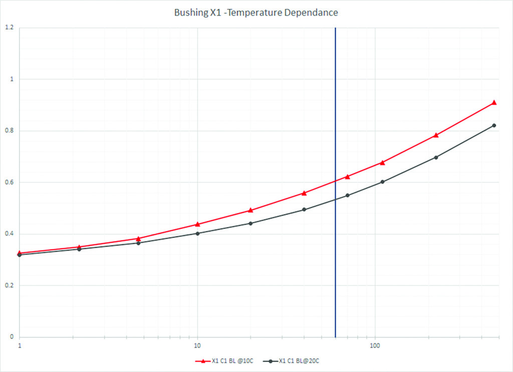
Figure 5: Bushing PF Temperature Dependence
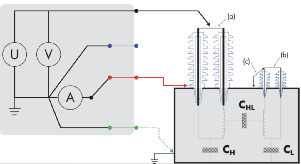
Figure 6: Effective Shorting and Grounding Techniques
Correct Handling of the Capacitance Tap
In a capacitance graded bushing, the main purpose of the test tap component is to provide access to measure the bushing capacitance and power factor. The voltage tap can also be used to measure permanent voltage or to monitor PF or partial discharge online.
When testing transformer bushings, all bushing tap caps should remain installed (closed) except the bushing under test. Since the test voltage is applied to a group of bushings, any unused test tap will have a potential difference if not grounded. The voltages that can be developed at open test taps may generate leakage current that not only can affect the PF results, but also severely damage a bushing and pose a safety hazard for the individuals performing the tests.
Special care should also be observed to properly connect the test leads to the capacitance tap; in some cases, adapters are needed to achieve a suitable connection while maintaining isolation from ground. These adapters are usually provided by the test set and/or bushing manufacturer.
Grounding and Shorting Techniques
When performing power factor and capacitance measurements on transformer bushings — both single- and three-phase — a well-known practice is to short all the bushings of the same group (same voltage level) together to form an equipotential section of the transformer with each winding group when performing a test (see shorts (a) and (b) in Figure 6).
When test voltage is applied in a given test, all bushings of that group will be at the same potential with respect to ground due to the short between them. On groups of untested bushings, a second auxiliary connection to ground is necessary (connection (c)) to avoid development of floating potentials that — just as open test taps — can be hazardous for personnel taking the measurements.
In addition to the safety factors involving shorting and grounding groups of bushings during power factor and capacitance measurements, these connections will also be useful when facing situations involving surrounding energized overhead lines and equipment, which can cause unwanted induced voltages. These voltages, in conjunction with the winding inductance of the transformer, as well as the stray capacitance between the windings and the bushings insulation, can lead to measurement errors.
Eliminating Surface Leakage Currents
Humidity and contamination will cause increased surface leakage currents that affect PF results, resulting in high or negative PF values or random values when the test is repeated. The effect of the surface leakage can be minimized by cleaning and drying the surface of the bushings or by using guard collars to bypass the leakage current.
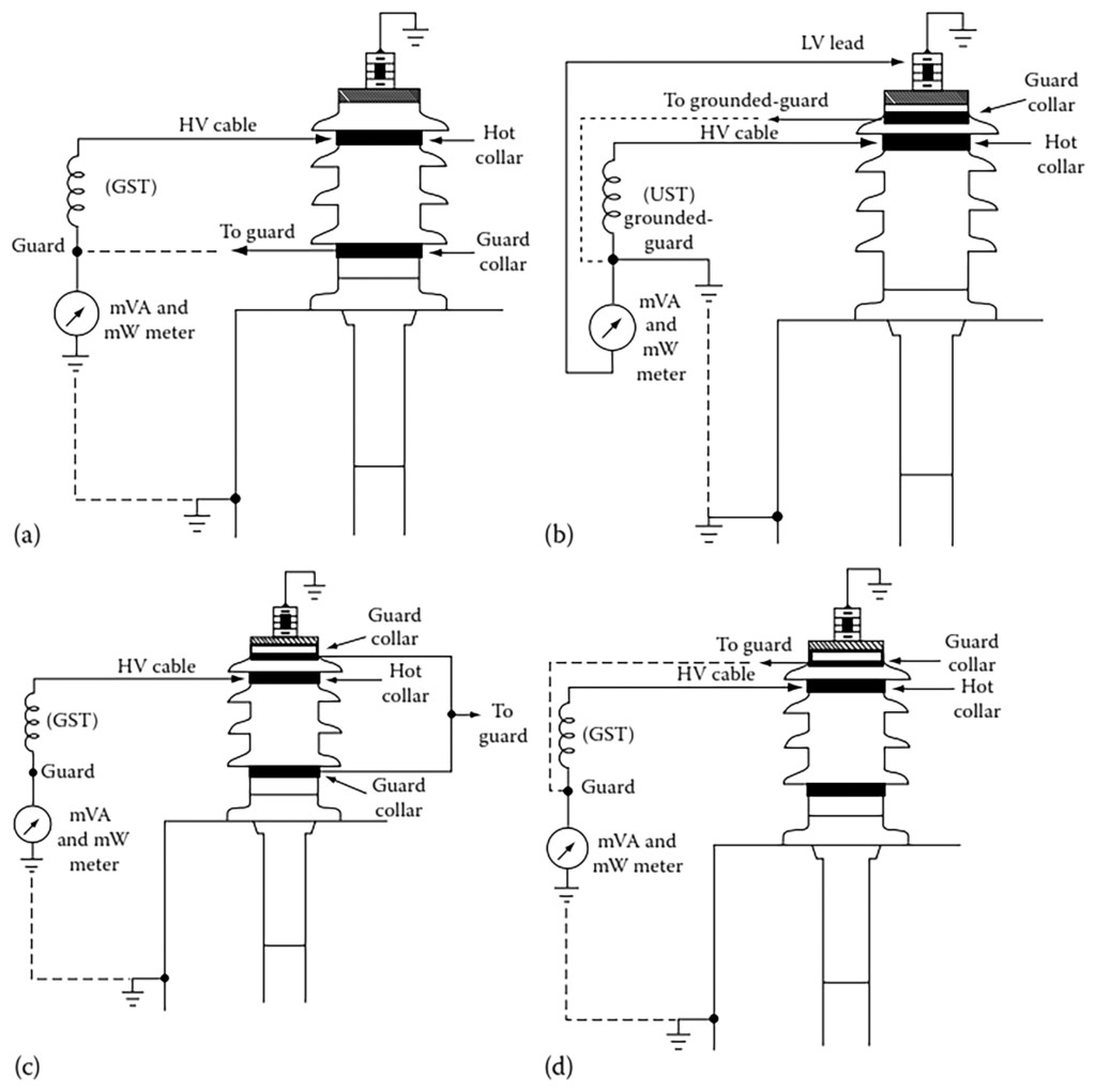
Figure 7: Hot Collar Test Setup: (a) GST Mode; (b) UST Mode; (c) GST-G with Guard Above and Below; (d) GST-G with Guard Above
When cleaning the bushing, special attention should be given to the test tap. Any adapter being used should also be in a clean and dry condition. A clean, dry cloth and window cleaner with ammonia is recommended. If any other cleaning agent is considered, it should not contain any hygroscopic substance, like isopropyl alcohol; it will clean, but it will absorb moisture from the air, worsening the condition.
After cleaning, consider polishing the porcelain to avoid accumulation of contamination. In the end, the wrong polishing agent may cause a sticky layer that will increase contamination or moisture accumulation. If needed, use a very thin layer of car wax, liquid hand soap, or any electrical insulating compound, such as Dow Corning #4.
When using the guard collar, GST-g test mode must be selected so that the current being diverted through the cable is bypassed from the measurement. Using the UST mode when possible will also eliminate the effect of leakage current from the measurement.
Hot Collar Test
A hot collar test generates a localized high-voltage stress by using and energizing a conductive collar around the porcelain. This can determine dielectric losses (watts and current, as PF is not analyzed) through various sections of any bushing when troubleshooting high PF results. It is useful to detect cracked porcelain, deteriorated cement joints, gasket leaks, or faults within condenser layers in condenser-type bushings, as well as to check the oil level of oil-filled bushings when normal oil level readings have been established or when comparing to bushings of the same type. If an abnormal mA or watts reading is obtained when the test is performed under the top petticoat, the test should be repeated under the second petticoat and move further down until normal readings are found.
The hot collar test can be performed with any of the test modes — GST, GST-g, UST — using one or multiple collars depending on the anticipated outcome of the troubleshooting (Figure 7 from Paul Gill’s Electrical Power Equipment Maintenance and Testing).
Guidelines for evaluating hot collar data:
• Watts loss
– <100 mW: Acceptable
– ≥100 mW: Unacceptable, possible contamination
• Current
– Within 10% of similar bushings: Acceptable
– <10% of similar bushings: Unacceptable, low level of liquid or compound, possible faults within condenser layers
NBDFR: An Alternative Technique
Narrow band dielectric frequency response (NBDFR) is an alternative technique to troubleshoot and investigate inconclusive PF results. It consists of multiple PF tests at different frequencies in a range of 1 to 500 Hz. Incipient or emerging changes in resistive losses at 60 Hz PF are too small in comparison to the capacitive component, which is proportional to the frequency of the total current. At lower frequencies, the capacitive component is smaller but the resistive component remains unaffected, becoming more predominant and resulting in an increased PF.
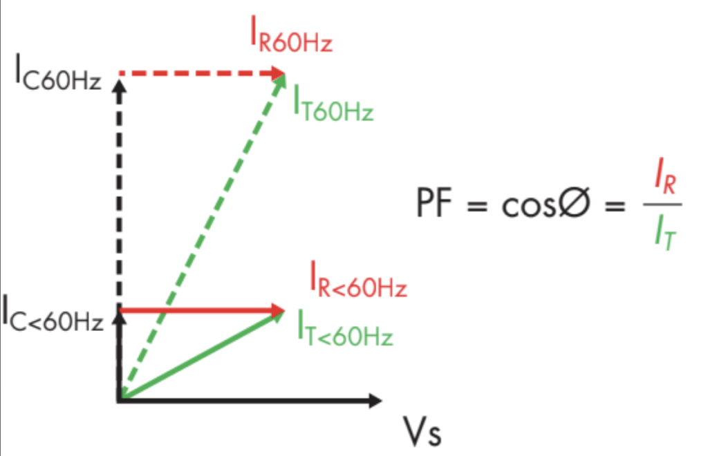
Figure 8: Effect of Variable Frequency on PF Measurement
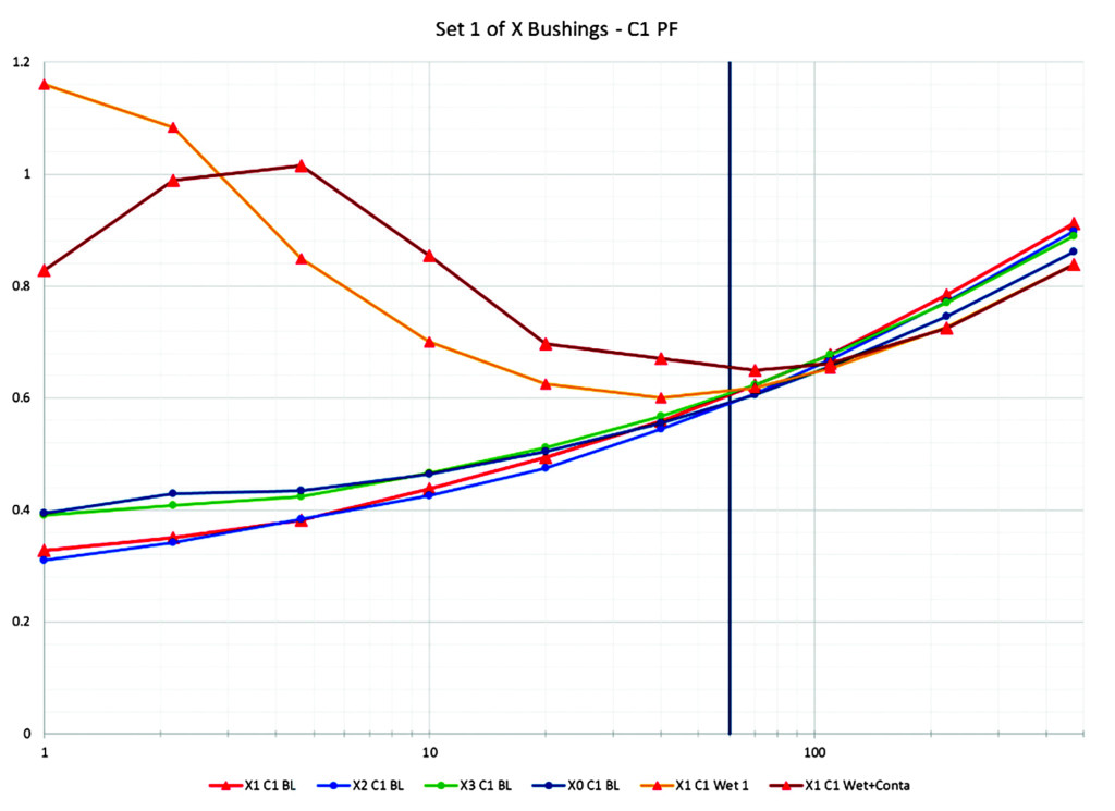
Figure 9: NBDFR tests: 4 Baseline Measurements, 1 Wet Bushing, 1 Wet+Contaminated Bushing
This technique makes it possible to confirm whether apparent good PF results are good or reveal a developing problem at an early stage.
Figure 9 shows the C1 NBDFR of four low-voltage side bushings under normal conditions (BL) and under wet and contaminated conditions (X1). The set of four BL measurements show a PF result around 0.6% at 60Hz. The measurements at 60Hz under wet and contaminated conditions are similar or slightly increased PF but are low enough to be inconclusive. However, the low-frequency results show increased PF predominantly below 10 Hz.
A second example (Figure 10) illustrates a case of four low-voltage bushings exposed to the same loading/thermal profile and environment. The 60 Hz results are below 0.5% and almost identical; this result will not trigger any investigation or action. The NBDFR result shows that X3 has higher losses, yet unnoticeable at 60 Hz, enabling a decision on effective remedial actions.
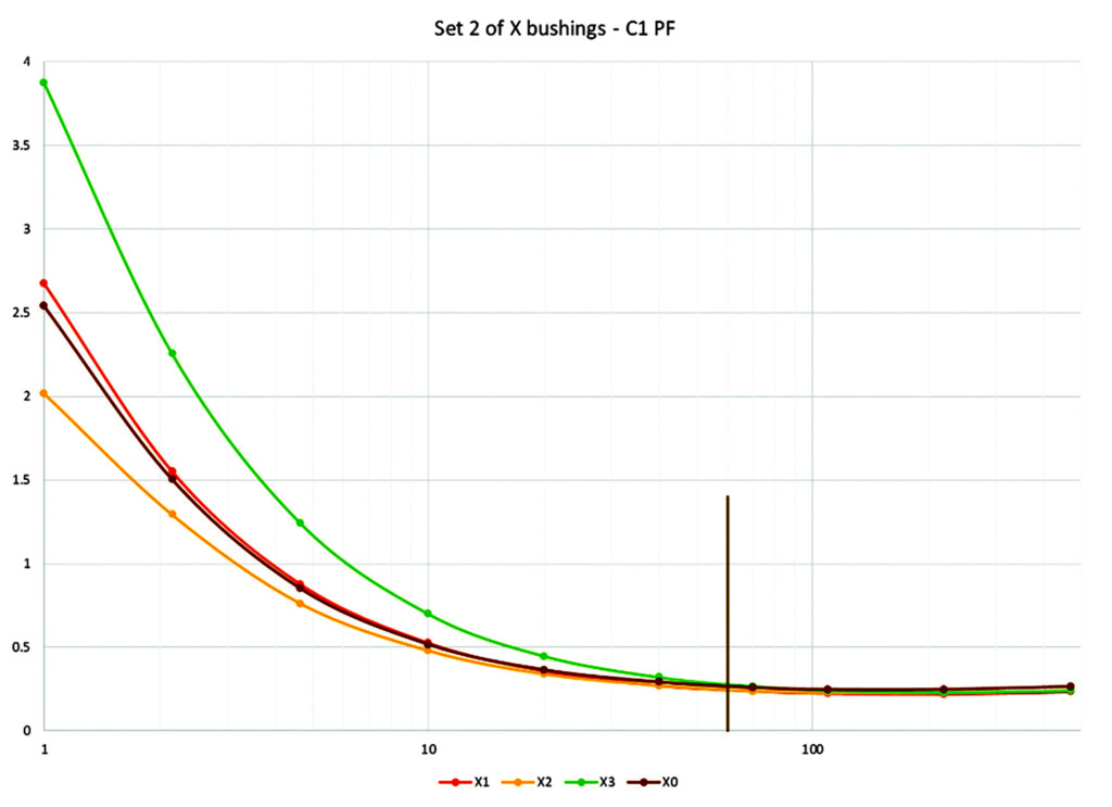
Figure 10: NBDFR on 4 Low-Voltage Bushings
Conclusion
Field tests of PF and capacitance of bushings are very valuable in assessing a bushing’s insulation integrity, but these tests are susceptible to measurement errors due to external factors. Following the best practices outlined here will help an individual find the cause of an abnormal reading or ensure those results are an indication of a deteriorated insulation system or an actual failure.
Another important source of measurement error is the temperature dependency of PF, which can be corrected using the ITC method. Alternative test procedures such as NBDFR measurement provide extra information about the condition of the insulation system, thus enabling the user to make a more informed analysis of the results.
References
Gill, Paul. Electrical Power Equipment Maintenance and Testing, Second Edition, CRC Press, 2009.
United States Dept. of the Interior Bureau of Reclamation, Facilities Engineering Branch, Denver Colorado. “Testing and Maintenance of High-Voltage Bushings,” August 2000.
Zhang, S. “Analysis of Some Measurement Issues in Bushing Power Factor Tests in the Field,” IEEE Transactions on Power Delivery, Vol. 21, No. 3, July 2006.
Robalino, Diego M. “Accurate Temperature Correction of Dissipation Factor Data for Oil-Impregnated Paper Insulation Bushings: Field Experience,” October 2011.
Megger. “Delta4000 Applications Guide,” 2010.
Werelius, P; Ohlen M; Cheng, J; Robalino, D. “Dielectric Frequency Response Measurements and Dissipation Factor Temperature Dependence,” 2012.
IEEE Std. C57.19.00–2004, General Requirements and Test Procedure for Power Apparatus Bushings.
IEEE Std. C57.19.01–2000, IEEE Standard performance Characteristics and Dimensions for Outdoor Apparatus Bushings.
IEEE Std. C57.19.100–2012, IEEE Guide for Application of Power Apparatus Bushings.
IEC 60137, Insulated bushings for alternating voltages above 1000V, Edition 6.0, 2008.
Breazeal, Robert C. “Unlocking the Mysteries of Narrow Band DFR,” NETA World, Fall 2019.
 Daniel Carreño is an Applications Engineer with Megger specializing in transformer testing, batteries, and high-voltage circuit breakers. His previous experience includes working for power transformer manufacturers in the United States and Mexico. Daniel is an IEEE-PES member and actively participates in substation equipment condition assessment and applications development. He graduated from Instituto Politécnico Nacional in Mexico City, with a BS in mechatronic engineering.
 Abel González Gómez has been an Applications Engineer for Megger, LTD in Markham, Ontario, since 2013. His research areas are analysis operation, control and protection of electric power systems, and the application of artificial intelligence and soft computing techniques. Abel previously worked as an Assistant Professor for the Faculty of Electrical Engineering at the Universidad Central de Las Villas, Cuba; as a Teletraffic Engineer, Control Engineer, and Head of the Marketing Department for the Cuban Telecommunications Company; as a Professor of marketing for the Universidad Central de Las Villas, Cuba; and as a Design Engineer and Applications Engineer for Arteche Medicion y Tecnologia in Zapopan, Jalisco, Mexico. He received his BS and MS in electrical engineering from the Universidad Central de Las Villas, Cuba.
 Volney Naranjo has been with Megger for over eight years as an Application Engineer focusing on power transformers, high-voltage circuit breakers, battery, and power quality testing. He has over 17 years of experience working in the power engineering industry, providing professional services for design, and testing and commissioning of power systems as a Field Engineer and Project Manager. Volney is a member of IEEE-PES. He graduated from the University of Valle in Cali, Colombia, with a BS in electrical engineering.