

A power system uses various elements within protective relay schemes, and having a thorough understanding of the theory behind these protective elements is more than useful — if not required — for anyone who comes in contact with them. Design engineers who must execute calculations based on system characteristics and machine capabilities and field technicians who conduct testing, calibration, and troubleshooting on protective elements are the two roles most exposed to protective relay elements. Understanding the theory behind their operation is critical to their success in calculating settings and verifying the element is operating correctly according to those settings.
The function and purpose of common elements found in many applications generally remain the same no matter where in the system they are utilized. However, some elements were designed not only for specific applications, but also for a specific piece of machinery or apparatus within the grand scheme of the power system.
Two elements that were designed for a specific application, whether machine or apparatus, are the distance element and the loss of excitation element.
In addition to sharing common ground on the stigma of being complicated, the distance element and the loss of excitation element share a common characteristic that detects abnormal system conditions regardless of their specific application. This common characteristic is changes in system impedance as plotted on an R-X diagram. The goal of this article is to establish the rules and fundamentals of the R-X diagram and then to walk through each element in a manner that is not typically used to explain them. A secondary goal is to break through the assumption that these elements are complicated.
The R-X Diagram
Understanding the application of these elements requires a review of the R-X diagram. Figure 1 illustrates a Cartesian plane used to plot impedance (Z) values.
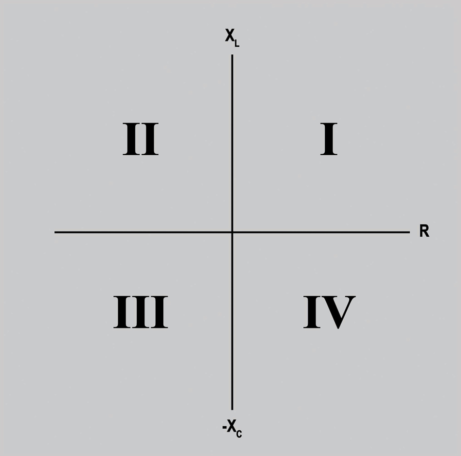
Figure 1: R-X Diagram
The x-axis quantifies resistive (R) values within an electrical circuit; the y-axis quantifies reactance (X) values. To explain the values within any Cartesian plane, we start with quadrant I. No matter how the Cartesian plane is used, we deem quadrant I the normal quadrant. The mathematics rules established in trigonometry inform us that positive angles rotate in a counter-clockwise direction starting from 0° (the x-axis). Quadrant I is the first quadrant passed through for a positive angle.
These exact rules are followed in phasor or vector diagrams used to quantify voltage and current. However, in an R-X diagram, we plot the combined resistance (R) and reactance (X) of a power system. The combined resistance and reactance of a power system is quantified as impedance (Z) and is dependent on the characteristics of the connected loads.
According to the U.S. Energy Information Administration’s Independent Statistics and Analysis, 48.2% of energy in the United States is utilized for machine-drive equipment. This only accounts for large industrial processes where inductive motors are used throughout manufacturing processes; it does not account for the remaining inductive loads found in commercial and residential applications. Given this information, it is safe to assume that the majority of loads connected to the power system are inductive (XL). Inductive reactance loads have a characteristic that causes current to lag the applied voltage. Therefore, because the power system loading characteristic is made up of inductive loads, the “normal” quadrant I illustrates lagging load characteristics.
Direction of Rotation
This information sets up the first rule we must follow: The counter-clockwise direction is for lagging angles (Figure 2). This is the opposite of phasor or vector diagrams used for voltage and current where counter-clockwise rotation quantifies the leading angles.
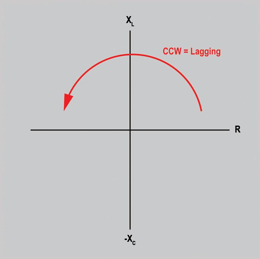
Figure 2: Establishing Direction of Rotation
Within the R-X diagram, this allows us to understand that all angles in the clockwise direction are leading. Impedance values found in the clockwise direction represent capacitive reactance values (-XC). Now, by understanding direction of rotation, we have established that inductive reactance (XL) is quantified as positive on the y-axis, and capacitive reactance is quantified as negative on the y-axis. With the established rules for the R-X diagram, we now take a look at our first protective element that utilizes changes in system impedance to detect system disturbances.
Distance Element
The distance element is found in power systems primarily to protect transmission lines that can extend for hundreds of miles and can also be found on distribution systems that extend considerable distances atypical for their normal application. When implementing distance protection during the design phase, the properties of the system must be considered. The reactance properties of the conductor plus the distance the conductor travels establish the foundation for what normal system condition appears to be. Furthermore, other environmental impacts, such as the manner in which the conductors are physically arranged in relation to each other and their physical distance from the earth, contribute to the reactance of the conductors.
Traditionally, distance elements are configured into multiple zones. These zones are set at different impedance values that increase from the point of measurement or point of origin. For this discussion, the shape of the protective zone is the mho circle, illustrated in Figure 3. The distance element will operate for any value of system impedance that is located within the mho circle. For any value of impedance outside of the mho circle, the distance element will not operate, and in electromechanical relays, restraining torque will prevent the mechanical contacts from closing.
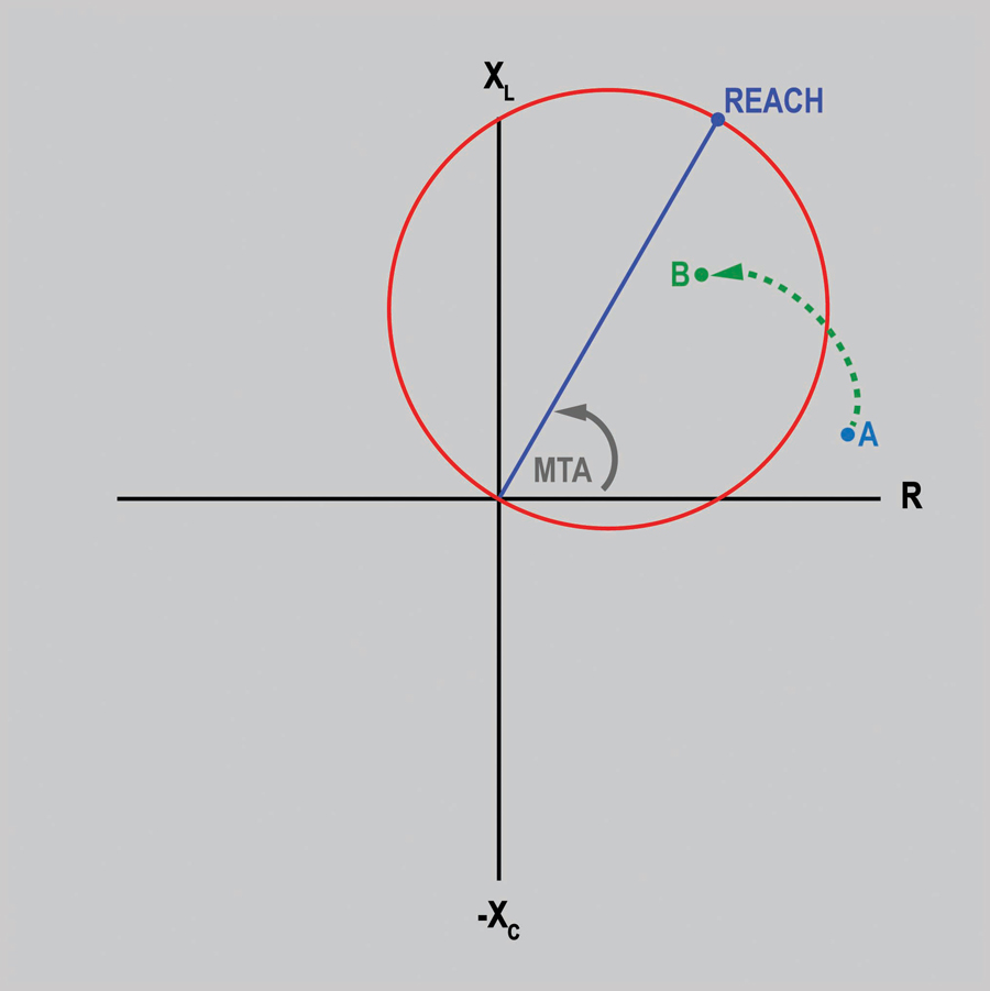
Figure 3: Distance Element
Reach. The first setting of the mho circle to discuss is reach. The reach of the characteristic is the primary property that sets up the diameter of the circle, and its value is set to equal the maximum impedance value at which the zone is to operate.
Maximum torque angle. The next property is the maximum torque angle (MTA). This quantity is determined by the normal system impedance when unloaded for this application. Typical values for the angle found on transmission lines are between a lagging, counter-clockwise direction at 60–75 degrees. The values will match the unloaded impedance characteristic of the transmission line being protected. The reach of the characteristic extends from the point of origin at the MTA, which completes the properties of the protection zone discussed in this article.
System impedance. During normal conditions, system impedance will typically be located just above the x-axis, illustrated by point A in Figure 3. The distance of point A from the point of origin is directly proportional to the value of system impedance, and the angle in which it is located is proportional to system reactance. As shown, during normal system operation, the impedance of the system is outside of the mho circle; therefore, the element does not operate.
The fault condition(s) in which distance elements operate are faults between phases, i.e. phase-to-phase, phase-to-phase-to-ground, etc. In any case, when a phase-to-phase issue occurs, the associated phase currents will increase due to the decrease in line impedance and the possible loss of load impedance as well. With the increase in current, the impedance value will decrease. Therefore, the reactance of the system causes an angular shift toward the MTA. An example of how this condition appears is shown by the dashed green line landing at point B. The distance element will operate as soon as system impedance is within the mho circle and will not wait to operate until system impedance reaches point B.
Loss of Excitation Element
Loss of excitation (LOE) elements, or loss of field, are found primarily on synchronous generators but can also be found on synchronous motors. The primary purpose of LOE protection is to prevent excessive reactance swings on the power system that will cause heating of all components within the system. Within a synchronous generator, a regulator is utilized to maintain the produced voltage at a constant set value. Without a voltage regulator, the generator terminal voltage would not be capable of supporting load changes that would cause the voltage to either sag or spike as loads are applied or removed. The simplest way to look at this issue is that, if we cannot control the voltage on the power system, then current is going to change accordingly. Ohm’s Law and the nature of power flow establish that when voltage changes, current will change as well.
Maximum torque angle and the mho circle characteristic are also utilized by the LOE element as in the distance element. The MTA for LOE elements is typically located at 90 degrees in the leading clockwise direction. As shown in Figure 4, because the MTA is at this angle, the mho circle is found in a different region of the RX diagram when compared to the distance element.
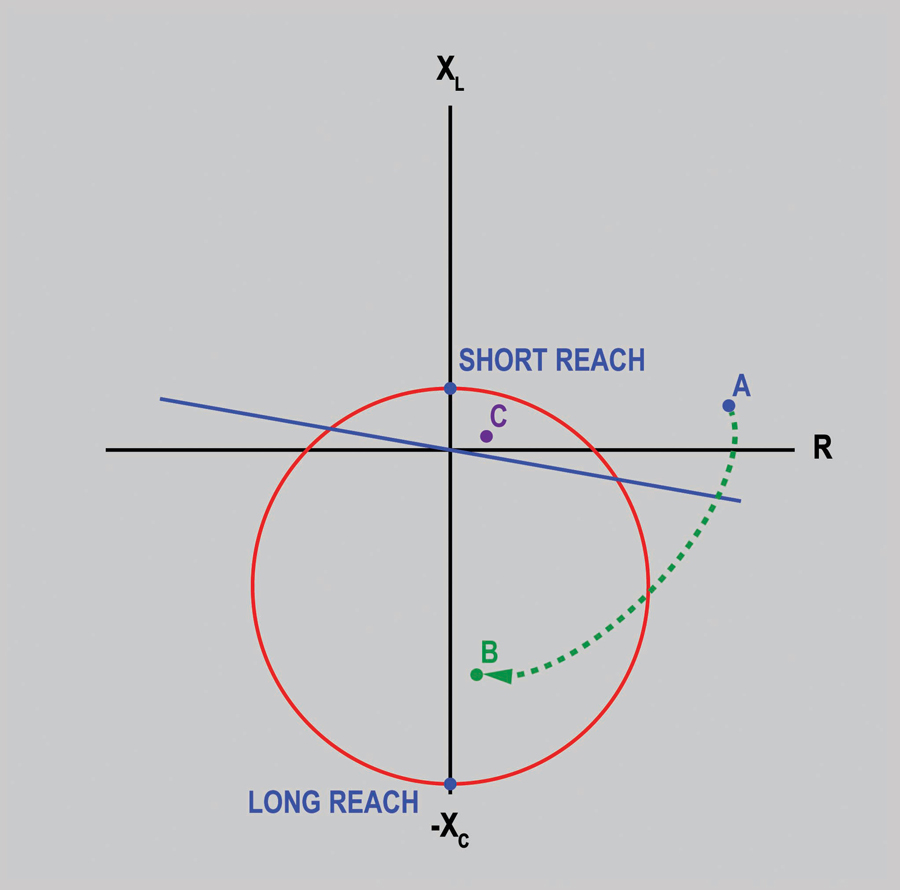
Figure 4: Loss of Excitation Diagram
In this example, the diameter of the mho circle depends on the location of the long reach and the short reach. The long reach sets the bottom point of the circle. The short reach sets the top of the circle. Typically, the long reach has an individual setting. The short reach, however, is generally established through a setting termed “offset.” The offset not only determines the physical distance from the point of origin, but it also determines which direction on the y-axis the short reach point is located. With a negative offset, the short reach will be located below the x-axis; with a positive setting, the offset will be located above the x-axis. Figure 4 depicts an LOE characteristic that has a positive offset. The LOE element utilizes the mho circle exactly the same as the distance element: When system impedance is outside of the circle, the LOE element does not operate and send a trip signal.
Directional Unit
The final property of the LOE is the directional unit shown as the blue diagonal line in Figure 4. The directional unit is used to prevent load encroachment caused when a generator is heavily loaded and the system impedance is very low. During this condition, the system impedance could very well be within the mho unit, point C. However, the directional unit will prevent the unit from tripping because the relationship between voltage and current is above the directional unit characteristic.
In a normal system, system impedance will typically land just above the x-axis shown as point A. During this state, system impedance is outside of the mho circle and above the directional unit, which prevents the LOE from sending the trip signal.
During a faulted system, loss of excitation will cause the voltage to decay at the generator terminals. This will cause the impedance of the system to decrease and swing toward the MTA as was shown as the dashed green line toward point B. As soon as the impedance enters the mho unit and is below the directional unit, the LOE element sends the trip signal. Like the distance element, the LOE element does not wait to operate until reaching point B, but operates as soon as the impedance of the system breaks the edge of the circle.
Conclusion
While these elements are extremely proficient at identifying the conditions for which they are designed, it takes all elements together to provide complete protection for a power system. The most complex element can without a doubt have inefficient means of identifying a fault condition, whereas the simplest can. A final note about the elements: A number of additional options can be found within each of them that are not discussed in this article. My ultimate goal was to present the information in a manner some may not have been exposed to yet in their journey of learning about protective relay elements.
References
U.S. Energy Information Administration (EIA). Independent Statistics and Analysis, August 28, 2020. Retrieved September 29, 2020, from https://www.eia.gov/energyexplained/electricity/use-of-electricity.php.
 Ralph Parrett is a United States Navy veteran with over 13 years of professional experience relating to electrical safety and maintenance training. During his time at AVO Training Institute, his proven dedication to training led to his position as Manager of Content & Delivery. His passion has always been to provide a topnotch training experience to ensure his students are more effective and safer when they return to the workplace. Ralph has extensive knowledge of maintenance, repair, and troubleshooting of control and instrumentation, relay logic systems, ABB control systems, central control station programs, power system equipment testing and maintenance, and other various types of equipment. He has developed and taught theory, operation, maintenance, and safety of various engineering systems.