
The Institute of Electrical and Electronic Engineers (IEEE) Standards Association recently approved the publication of IEEE Std. C57.161–2018, Guide for Dielectric Frequency Response Test. The work was developed within the IEEE Transformers Committee and the Dielectrics Subcommittee. The industry needed a document to better understand the field application of a non-intrusive and non-destructive method to assess the condition of oil-paper insulation in power and distribution transformers.
Over the last two decades, other technical references presented the development of dielectric frequency response (DFR), aka frequency domain spectroscopy (FDS), specifically its application for power and distribution transformers with oil-impregnated paper insulation. CIGRE Technical Brochures 254, 414, and 445, as well as IEEE Std. C57.152, addressed the importance of the research and the benefits of the method as applied to power and distribution transformers.
The IEEE Transformer Committee initially formed a task force to recommend (or not) the need to develop a guide describing the application of DFR on oil-impregnated transformers. From the initial step of forming the task force to the publication of the guide, the contributions and participation of specialists, end-users, testing equipment manufacturers, transformer manufacturers, and academia made it possible to produce a practical and comprehensive guide for using DFR technology and interpreting a transformer’s insulation dielectric response in the frequency domain.
DFR History
Around the mid-1900s, the frequency domain response was thoroughly studied, and the definition of dielectric losses at power or line frequency (50/60Hz) turned out to be a great success for transformer manufacturers, end-users, and testing service companies. Technology evolved, however, and electronic components and control devices opened the door to a wider band frequency spectrum to analyze different insulation materials.
In 1996, WaBtech AB in Sweden brought the first portable device for DFR testing in the field to the market. Dr. Peter Werelius and Bjorn Bengtsson introduced the insulation diagnostics analyzer (IDA) mainly for cable and transformer testing. The practical application of DFR in the field generated interest in the industry, and international organizations took the lead on investigating this new technology that was revolutionizing testing practices in the field.
In 2002, CIGRE developed Technical Brochure 254, “Dielectric Response Methods for Diagnostics of Power Transformers.” This report from Task Force D1.01.09 focused on three dielectric response techniques: return voltage measurements (RVM), dielectric spectroscopy in time domain (TDS), and dielectric frequency domain spectroscopy (FDS). The task force concluded that (a) all three methods reflect the same fundamental polarization and conduction phenomena in transformer insulation and (b) the definition of moisture in solid insulation by time domain and frequency domain responses requires mathematical modelling and a good understanding of the dielectric properties of insulation system components.
In 2010, CIGRE continued the work and published Technical Brochure 414, “Dielectric Response Diagnoses for Transformer Windings,” which combined the acquired practical experience with the mathematical modelling approach to determine testing best practices. The document covers the fundamentals of the X-Y model, measurement configurations, test performance — and perhaps the most important part — case studies and comparative analysis using Karl Fisher titration (KFT) to validate using dielectric response methods to detect moisture estimation in solid insulation.
The technology was widely accepted in the field. Continuing the work, CIGRE Working Group A2.34 incorporated the dielectric response methods in time and frequency domain into Section 5.1.3 of Technical Brochure 454, which was published in 2011. Dielectric response methods are included as “Special or Advanced Measurements.” DFR or FDS is an advanced testing technique used in the field to determine the water content in the solid cellulose insulation of oil-paper insulation and detect insulation failures and insulation contamination. Moisture content in solid insulation is derived from field testing and mathematical modelling, and a database source is compared against limits given for dry, moderately wet, and extremely wet insulation in IEC 60422. IEC 60422 states that although the determination of water content in transformer paper by measuring the water in oil has been frequently described, practical results are often not in line with the theoretical predictions. All calculations and correlations of the water content in oil and the water content in the oil/paper system depend on the equilibrium state between the insulating oil and the oil/paper system.
In North America, the IEEE Transformer Committee revised IEEE Std. 62, Guide for Diagnostic Field Testing of Electric Power Apparatus — Part 1: Oil filled Power Transformers, Regulators, and Reactors. One of the fundamental reasons for revising this document was the application of new testing techniques that were not previously described but were considered important to help manufacturers and end-users meet current requirements, especially in the field. It is interesting that IEEE 62 (R2005), Section 6.3.12 provides two tables with general guidelines for interpreting data expressed in percent saturation of water in oil and in percent moisture by dry weight of paper.
The work carried out by the IEEE Transformer Committee ended with the 2013 publication of IEEE Std. C57.152, Guide for Diagnostic Field Testing of Fluid-Filled Power Transformers, Regulators and Reactors. The amount of information assembled in this document is difficult to describe in just few lines, but this guide added Informative Annex G, which provides a brief description of the dielectric frequency response method and its interpretation for oil-paper insulation systems in power transformers.
IEEE Guide for Dielectric Frequency Response Test
The continuous work of IEEE and its members is well-reflected in IEEE Std. C57.161, IEEE Guide for Dielectric Frequency Response Test, which is applicable to liquid-immersed transformers. The guide includes a thorough description of the DFR method, comparative analysis of line-frequency power factor and the dielectric response in a wide frequency spectrum, recommendations for instrumentation, procedures for performing the tests, and guidelines for interpreting the data. The application of DFR allows testing in the factory and in the field.
After a general overview, Section 4 introduces the DFR method. DFR is a non-intrusive and non-destructive off-line testing technique performed in the frequency domain to determine the moisture content of a transformer’s solid insulation and the conductivity of the liquid insulation. This paragraph covers one very important characteristic of the dielectric response: It can discriminate between the effects of moisture versus contamination in liquid or solid insulation.
Section 4 describes several important facts.
- First, DFR, as with any other dielectric response method, depends on the unique dielectric properties of the material, the electric field, and the temperature of the specimen at the time of the test.
- Second, DFR follows the same measurement principle as the line-frequency power factor test, but the excitation signal applied by DFR instruments varies frequency in the range from 1 kHz down to 1 mHz (typical range at 20°C). The complex impedance of the dielectric system is measured at different frequencies, and the dielectric response is plotted as percentage dissipation factor, permittivity, or capacitance as a function of frequency.
To evaluate the condition of the insulation system, the modelling algorithm requires specific information. The normally fixed information is:
a. Liquid insulation relative permittivity (εr)
b. Thermal activation energy for solid and liquid insulation
c. Temperature of the insulation under test
The outcome of the test will provide:
- Liquid insulation conductivity (σ)
- Moisture in solid insulation (μ)
In addition to modelling, it is important to understand that the test is performed in the field following the same instrument-to-object hook-up principles as those used for power factor/dissipation factor testing at line frequency. Figure 1 depicts the hook-up diagram of the DFR test set to a commonly used two-winding transformer.
Section 5 provides best practices and configurations to perform the test in the field. As in any other electrical test, the very first recommendations are related to safety. For many readers, safety is not just a best practice; it is a life style. Therefore, the local and federal regulations required to perform the test as well as the safety instructions provided by the test set manufacturer must be followed. An additional advantage of DFR is that the test involves a low-voltage excitation signal, typically ≤ 140VRMS.
Working conditions in the field might not be optimal. Section 5 provides guidelines to minimize the effect of external factors on test performance as well as the measurement configurations. At this stage, the reader should be aware that the most accurate estimation of moisture in the solid insulation is related to the test between windings in an ungrounded specimen test (UST) mode. In a two-winding transformer, the capacitance of interest is the inter-winding insulation between the high- and low-voltage windings represented in Figure 1 as CHL. Other insulation systems between the high-voltage winding and ground (CH) or between the low-voltage winding and ground (CL) are susceptible to the influence of bushings and other components, such as tap changers, inside the transformer. Nevertheless, UST measurements are often taken to identify non-typical responses related to contamination or degradation of the insulation system.
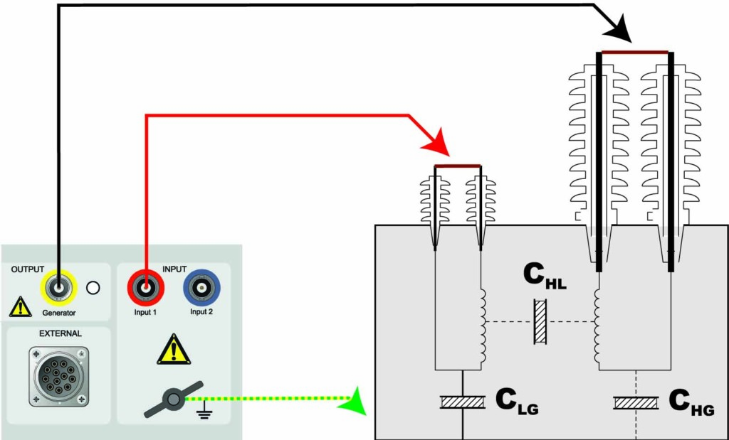
Figure 1: Hook-Up between DFR Test Set and Two-Winding Transformer
Section 6 provides the guidelines to generate the test report, including an example of the report.
The most important part of the guide is undoubtedly Section 7, Measurement Analysis and Interpretation. This section provides the differences between the dielectric response of liquid and solid insulation, graphically represented in Figure 2. Liquid insulation dielectric properties can be described by a simple parallel RC-circuit: The capacitance represents the liquid permittivity; the resistance represents the liquid conductivity. The dielectric properties of solid insulation are more complex; both capacitance and losses vary with frequency in a manner that cannot be described by a simple parallel or series RC-circuit.
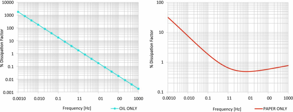
Figure 2: a) DFR of Mineral Oil; b) DFR of Paper Only
After a clear description of the behavior of the materials under an alternating excitation signal in a wide frequency spectrum, various factors affecting the dielectric response are described. One of the most important factors to consider is the presence of noise (EMI) in the surrounding test area. To overcome the effect of EMI on the measurement signal, use of a voltage amplifier is optional in the field, especially for low-capacitance specimens and tests at temperatures close to 0°C.
Four annexes are included in the document:
- Dielectric frequency response analysis — theory and validation
- Non-moisture related factors influencing the DFR measurements
- Examples of typical measurement challenges
- Bibliography
Conclusion
This article, which was originally published in Transformer Technology Magazine, represents a brief summary of a well-developed document provided by IEEE and its members. The author considers it imperative for asset managers, utility operators, transformer manufacturers, and testing service providers to acquire this document and follow the guidelines given.
 Diego Robalino, PhD, PMP, IEEE Senior Member, is a Principal Engineer at Megger, where he specializes in the diagnosis of complex electrical testing procedures. He has over 20 years of involvement in the electrical engineering profession with management responsibilities in the power systems, oil and gas, and research arenas. Diego is a member of the IEEE/PES Transformers Committee, a certified Project Management Professional with the Project Management Institute (PMI), and the General Chair for the IEEE/DEIS 2020 Electrical Insulation Conference. He is the author and co-author of multiple technical articles related to power, distribution, and instrument transformer condition assessment. Diego received his PhD in electrical engineering from Tennessee Technological University while doing research in power system optimization with a focus on aging equipment.