

The reliability of medium-voltage underground systems is a foundational element for the continuous performance of wind farms, particularly in regions with challenging environmental conditions. In a global context of increasing integration of renewable energy sources into the electrical matrix, failures in buried insulated cables not only affect system availability but also jeopardize operational and economic safety.
The investigation described in this case study was triggered by an unexpected shutdown in December 2019, when one of the collector circuits in a wind complex in northeastern Brazil experienced a phase-to-ground short circuit. This event prompted an extensive technical analysis aimed at understanding the immediate failure as well as the underlying systemic causes that could compromise the full operation of the plant.
The analyzed complex comprises eight wind farms, each equipped with ten 3 MW wind turbines. Each turbine operates at 690 V and is connected to a step-up transformer that raises the voltage to 34.5 kV, the standard value used in the medium-voltage underground collector network. This network consolidates the energy produced across the turbines and delivers it to a substation collector, which then transmits power via transmission lines to a central step-up substation. The collector network employs a 20/35 kV aluminum single-core cable with a nominal cross-section of 300 mm², soft temper, and round compacted construction, classified under stranding class 2. The cable features TR-XLPE insulation rated for 90 °C operation, longitudinal water-blocking, and metallic shielding with bare copper helically wound wires of at least 6 mm² cross-section. Its outer sheath is made of black high-density polyethylene (HDPE, ST7 type), ensuring mechanical strength and protection against environmental stresses.
The coastal region where the wind park is located features specific environmental characteristics, predominantly sandy soil and a humid tropical climate. While these conditions are favorable for wind generation, they impose demands on the design and operation of underground cables, especially regarding thermal dissipation. The thermal behavior of the soil, its compaction and moisture content, and the spacing between circuits become critical variables in determining the cables’ ampacity and the preservation of their dielectric properties over time.
INSPECTION AND ANALYSIS
Initial inspections revealed clear visual evidence of cable degradation. During the excavation of the trench where six three-phase circuits were buried, cracks, deformations, and fusions were found between the outer sheaths of adjacent cables along with signs of carbonization and melting of the polymeric coating (Figure 1).

This damage raised immediate concerns about the thermal integrity of the system, suggesting that the cables were operating beyond the manufacturer’s specified limits, particularly regarding the maximum continuous operating temperature of 90°C.
The methodology adopted for conducting the technical investigation was based on IEEE 1511.1–2010, IEEE Guide for Investigating and Analyzing Shielded Power Cable Failures on Systems Rated 5 kV through 46 kV,which provides detailed guidelines for analyzing failures in shielded medium-voltage power cables.
The standard classifies failure modes into six major categories:
- Mechanical
- Chemical
- Electrical
- Natural aging
- Thermal
- Other miscellaneous causes
Using this framework, technical hypotheses were formulated to correlate the observed visual symptoms with potential structural, operational, or environmental root causes.
Mechanical
Mechanical analyses were the first to be considered. The possibility of breaks in the metallic shield or deformations resulting from excessive bending during installation was investigated. Time-domain reflectometry (TDR) tests conducted on the end sections of the circuits showed proper continuity of the shielding, with no peaks or dips indicating breaks. In addition, visual inspections confirmed that the shielding wires were arranged uniformly and remained intact, with no signs of crushing or twisting.
Chemical
The hypothesis of chemical failures was also investigated, particularly due to suspicions of potential interactions between the soil and the cable’s outer jacket. In aggressive soils, or those containing contaminant chemical compounds, accelerated degradation of polymeric materials or corrosion of the metallic shielding may occur.
However, tangent delta tests indicated low dielectric losses, suggesting that the internal insulation was in good condition. The absence of records of chemical use in the area, combined with the observation of intact cables installed adjacent to failed ones, reinforced the conclusion that there was no systemic chemical agent present in the soil. Thus, chemical failure was also ruled out as the primary cause.
Electrical
The analysis of electrical failures focused on investigating possible voltage surges, lightning strikes, or partial discharge activity in the affected areas. Electrical testing, oscillographic analysis, and field inspections revealed no evidence of significant surges or localized insulation breakdown. Furthermore, the damage observed on the cables did not match typical patterns of electrical failure, which usually originate from the inside out, whereas in this case, the damage had clearly visible external origins.
Natural Aging
The hypothesis of natural aging was also dismissed based on the short operational life of the cables, less than three years, and the absence of water treeing signs in the laboratory tests.
Thermal
After ruling out the previous causes, attention shifted to the hypothesis of thermal failures. A comparison between in-service cable samples and new cables revealed significant darkening of the insulation, indicating early thermal degradation. This visual difference is shown in Figure 2, where the dark tone of the operating cable stands in stark contrast to the light color of the new cable, indicating exposure to elevated temperatures, possibly exceeding the continuous operating limit.
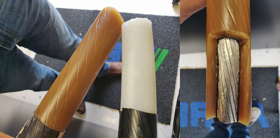
(B) Detail of the Insulation Cross-Section after Operation
The observed discoloration is not limited to the fault location. It extends across significant portions of the circuit where improper cable grouping and inadequate thermal backfill were applied. These segments experienced recurrent thermal stress, leading to visible changes in cable coloration. In contrast, areas where proper spacing between circuits was maintained and backfill was correctly implemented did not exhibit similar discoloration.
Considering this evidence, the design report for the circuits was reviewed with a focus on three key variables affecting thermal performance:
- Spacing between circuits
- Soil temperature
- Thermal resistivity
Field investigations revealed that the spacing between the trefoils was often less than the 30 cm specified in the design, reaching as little as 19 cm in some sections of the route, which severely impairs thermal dissipation between adjacent cables. Even localized reductions in spacing contribute to the formation of thermal hotspots, accelerating the aging of both the insulation and the outer jacket.
Regarding soil temperature, it was found that the project had adopted a standard value of 20°C, commonly used in temperate regions. However, measurements and meteorological studies of the site indicated an average of 28°C at the cable installation depth (90 cm), a value that compromises the current-carrying capacity of the conductors if not properly compensated for through other design factors.
Even more concerning was the underestimation of soil thermal resistivity. The project used values ranging from 1.0 to 1.5 K·m/W for various segments, whereas IEC 60287, Calculation of the Continuous Current Rating of Cables, recommends values between 2.5 and 3.0 K·m/W for dry sandy soils, precisely the conditions at the site.
Thermal simulations were carried out using different scenarios for soil resistivity and temperature. The results showed that with resistivity between 1.0 and 1.5 K·m/W, even under high temperatures, the cables operated below the 90°C threshold. However, with actual resistivities of 2.5 K·m/W or higher — as encountered in practice — the conductor temperature exceeded this limit in nearly all circuits. This confirms that the failure was not caused by electrical overloading, but rather by deficiencies in the thermal design of the installation, particularly due to the absence of thermally stable backfill, inadequate soil compaction, and reduced spacing between cables.
RECOMMENDED ACTIONS
At the end of the analysis, the study concluded that the root cause of the cable failures was sustained operation beyond the recommended thermal rating, with excessive heating induced by a combination of factors:
- Underestimation of thermal resistivity
- Failure in soil characterization
- Inadequate spacing
- Lack of clear guidelines for soil compaction
This situation led to accelerated material degradation, loss of dielectric properties, and the emergence of mechanical-thermal failures observed visually.
In response to this scenario, two primary actions were recommended.
- The first, corrective in nature, is the complete replacement of the affected cables, even in the absence of visible electrical failures, considering the accumulated damage and the risk of future collapse.
- The second, preventive in nature, involves redesigning the system with the implementation of low thermal resistivity backfill, increased spacing between trefoils, and specific measures to ensure proper soil compaction.
As a short-term palliative measure, periodic soil irrigation in the most critical areas was suggested to temporarily reduce thermal resistivity and improve heat dissipation. For the remaining circuits, applied voltage testing with monitoring via partial discharge and tangent delta measurements was recommended to detect latent failures and maintain the operational reliability of the system.
CONCLUSION
This case study illustrates how small inaccuracies in design parameters can lead to significant consequences in medium-voltage underground systems. In contexts of harsh climate and unfavorable soil conditions, neglecting thermal aspects can compromise asset longevity, cause substantial economic losses, and hinder the performance of renewable energy sources.
The analysis reinforces the need for an integrated approach that combines local measurements, laboratory testing, and engineering simulations to ensure the robustness of underground electrical systems in a sector that is increasingly strategic for the country’s energy future.
REFERENCES
- IEEE. IEEE 1511.1–2010, IEEE Guide for Investigating and Analyzing Shielded Power Cable Failures on Systems Rated 5 kV through 46 kV.
- IEC. IEC 60287, Calculation of the Continuous Current Rating of Cables.

Nilson Baroni Jr, PMP®, is the Operations Director of BAUR USA Corp. He is a Senior Electric Engineer with more than 34 years of experience leading teams and managing projects in engineering, operations, and maintenance of low-, medium-, and high-voltage electrical networks in the overhead and underground segments in the largest electric utility in Brazil (more than 7 million customers). Baroni is an international speaker on topics related to electric utilities.

Daniel Bento, PMP®, CEO of BAUR do Brasil and BAUR USA Corp. He is an electrical engineer with over 30 years of experience in medium-voltage insulated cable networks. Bento is a former coordinator of CIGRE Study Committee B1 on insulated cables and co-author of CIGRE Technical Brochures 773 and 924 on fault location and cable diagnostics. He was the technical lead for the entire underground distribution network in the city of São Paulo, Brazil.

Danilo de Souza, PhD, is a member of the technical standards committees of the Brazilian Association of Technical Standards (ABNT). He holds a PhD in energy from the University of São Paulo (USP) and is an Associate Professor at the Federal University of Mato Grosso (UFMT). He works in electrical safety, energy efficiency, and energy planning and supervises master’s and doctoral research at UFMT and USP.