
The National Fire Protection Association (NFPA®) revised its NFPA 70E, Standard for Electrical Safety in the Workplace in 2018 “to assist OSHA in preparing an electrical safety standard that would serve OSHA’s needs and that could be expeditiously promulgated through the provisions of…the Occupational Safety and Health Act.” Responsible electrical test instrumentation manufacturers accept 70E as a valuable guideline as they develop and incorporate specific safety features into their products. This provides electrical industry operators and supervisors with a reliable and convenient means to evaluate test equipment for safe operation. When purchasing, don’t just look at price and performance. Be familiar with, and unfailingly apply, the relevant safety standard designations.
NFPA 70 suggests ten design criteria to help you select the safest and most effective test equipment.
Arc Flash Protection
Perhaps the most important safety feature is conformance to IEC 61010-1 for arc flash/arc blast protection (Annex K.3 and Annex K.4). The standard defines creepage and clearance distances that must be maintained throughout the internal circuitry of test instruments and associated leads to prevent an arc during an external voltage disturbance. IEC 61010-1
sets design parameters that prevent these occurrences and labels them to indicate the maximum safe working environment, such as downstream from the service entrance, and specifies the maximum safe voltage rating of the system where the instrument can be used. Instrumentation should be correctly rated against the working environment. Beware of judiciously worded specs; some advertising states a category but fails to specify the maximum allowable circuit voltage.
Insulation Discharge
Without safety training, it is easy to understand a common misconception: When the switch is off, the electricity is off. And that is the danger — it’s not so! There are numerous counter examples, but in electrical testing, one of the most common is stored energy following an insulation test. These maintenance and troubleshooting tests are frequently performed to measure insulation resistance. They are performed with dc voltage for a number of reasons, including reading accuracy, size, and test instrumentation cost and efficiency.
Test equipment can store vast amounts of energy — enough to be lethal:
- Long cable runs — miles of parallel conductors separated by a layer of insulation, as well as windings in transformers, generators, and motors, with each turn separated from its neighbors — act as huge capacitors and store energy.
- Absorption that occurs in the insulating material as polar molecules align against the dc field is even more insidious because it discharges far less quickly.
At the conclusion of a test, a technician’s impulse is to disconnect the leads. But stored energy will discharge any way it can, including through a hapless operator. Tested equipment must be safely discharged to below 50 volts before it can be touched. (120.4, B 2: The procedure shall include requirements for releasing stored electric…energy that might endanger personnel.) And don’t attempt this by applying a dead short! Short-circuiting the item can create an uncontrolled cascading discharge that generates sparks and is dangerous and potentially damaging. Instead, apply controlled resistance and connect to ground. This task was heavily operator-dependent in old instrumentation. Rules of thumb were followed with the goal to overcompensate for the discharge time by basing it on a multiple of the test time. Five times the test duration was usually the rule. But the operator had to remember to do this. The earliest attempt at automation included a discharge circuit in the insulation tester. But the operator engaged this function through a separate selector position, so it was easy to forget or overlook in the haste to meet a work schedule.
Today, the tester does it all. A modern tester (Figure 1) can sense any extraneous voltage on the test item, measure it, and display it automatically, complete with visual and audible attention getters. All the operator has to do is observe the display as voltage decays. Resistive discharge sticks can still be applied, but they are not necessary; this speeds the process.
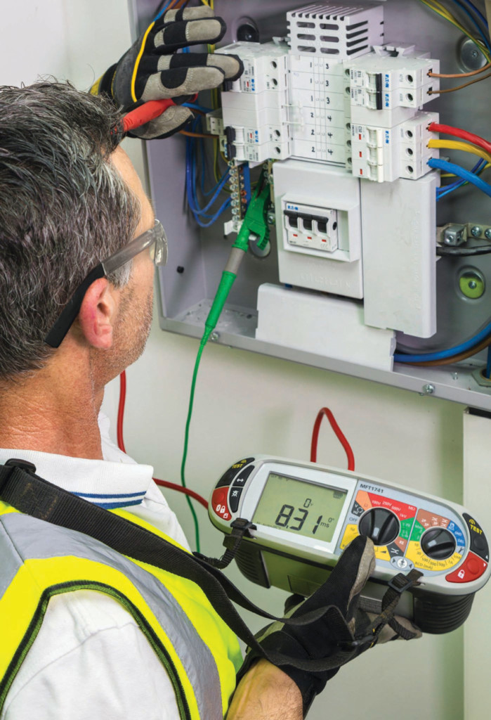
Figure 1: Multifunction Tester Checking Circuity for Safety and Performance Compliance
Live Volt Warnings
A wide range of quality instruments now provides automatic voltage warning. If the tester senses voltage on the test item, it beeps and flashes and often displays a measurement. (110.4 E: When test instruments are used for testing the absence of voltage on conductors or circuit parts operating at voltages equal to or greater than 50 volts, the operation of the test instrument shall be verified…) Some testers don’t even have to be turned OFF. Even the leads may have warning lights for situations where the test object is a stretch from the meter and the operator may not have visual contact with the display. If the line is deenergized when the test is started, but someone remotely throws a switch due to improper lock-out/tag-out, the indicators engage and the operator is promptly warned that the test object has become live. Some sophisticated models go a step further to protect both operator and instrument: They lock out the test. If a distracted operator disregards the warning and attempts the test, the tester refuses to engage the external circuit. For telecom/datacom testing, where low crosstalk levels are common, sophisticated models may only engage voltage protection above a specific value. This feature prevents harmless noise from constantly interrupting testing. Top quality testers retain this audible and visual warning function even if protective fuses have been blown.
Contact Detection
Multi-function testers are popular and convenient, but they present additional design challenges to maintain safety. Multimeters and insulation testers include both high- and low-resistance functions. In the haste of work and while switching from one test to another, the operator might momentarily leave a lead unconnected and dangling. This could become a dangerous source of voltage if the line became energized through carelessness or electrical fault. Testers with redundant safety will prevent switching from a high-impedance insulation test circuit to a low-impedance — hence more dangerous — continuity test until it senses that both leads have been connected.
Remote Operation
Most common electrical testing is performed manually. It is generally believed that avoidance of physical contact is enough to keep an operator safe. But an electric shock in the form of an arc can come and get you. Just as minute arcs can occur within electrical circuitry, massive arcs of 30 feet and more can be drawn in high-tension areas like substations and switchyards. Advanced instrumentation with remote control can keep the operator at a safe working distance, and other hazards can similarly be avoided. In some situations, it may be necessary to test large switchyard transformers from atop to keep leads short because long leads from ground level can pick up too much noise. But height itself can be a hazard. Operating a remote tester from ground level reduces climbing and enhances operator safety. Additionally, many maintenance tests must be performed on potentially faulted equipment that may explode if serious faults (dead shorts) are present. Safety requires performing such tests inside cages with the operator safely outside. Remote control makes this possible.
Transformer Over-Voltage Protection
Transformer turns-ratio testers are used to ensure turn-to-turn shorts don’t radically alter a transformer’s specifications. The recognized standard is tight: If the actual ratio between primary and secondary isn’t within 0.5 percent of spec, the transformer shouldn’t be in service. Old, hand-cranked ratio testers presented a serious safety hazard, especially in tandem with untrained operators. Connecting to a step-down transformer’s secondary and ambitiously cranking could produce an enormous and potentially dangerous voltage on the primary, often unknown to the operator. Modern testers include a built-in feature that automatically performs a low-voltage check to ensure the ratio is within a specified value before proceeding with the higher voltage required for the measurement. Correct lead connections are simultaneously checked.
Dual Ground
Testing contact resistance in circuit breakers on utility lines is potentially risky and calls for redundant safe working practices. In one clever adaptation, both sides of the breaker are grounded, since a fault can occur in either direction. But dual grounding creates a parallel current path through the earth that introduces significant error into contact resistance. Normally, one side must be lifted for the duration of the test, a practice that adds extra work and creates a potential hazard. By incorporating a current clamp into the tester’s measurement circuitry, superfluous parallel current can be measured and subtracted, giving an accurate measurement while keeping the operator safe.
MultiFunction Testing
Test equipment must be maintained not only for performance, but also for safety. (250.1: Personal safety and protective equipment such as the following shall be maintained in a safe working condition: (4) Test instruments…) Safety testers are now available with a full test regimen in a single tester. Called multifunction testers or portable appliance testers (Figure 2), these instruments have long been standard and are often required in the more highly regulated European market, but are only just being recognized in the United States.
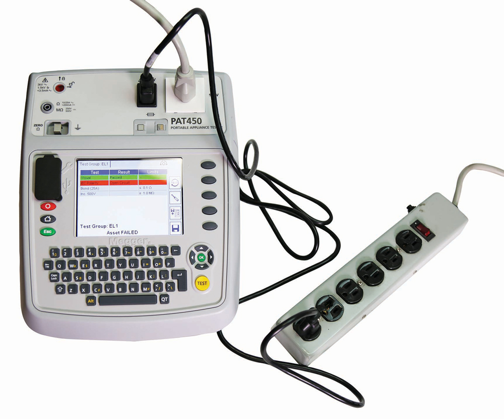
Figure 2: Portable Appliance Tester Performing Safety Check on Power Strip. Due to rough handling and being stepped on, power strips are often dangerous.
MFTs can test electrical instruments and tools for complete safety in a single operation, and models have been designed specifically to comply with NFPA 70E. Generally, the tested item is simply plugged into the MFT, a return probe is affixed, and the test regimen performs automatically in proper sequence, with the results evaluated and indicated against operator-entered criteria. Stored in a test record, the data provides an invaluable asset against third-party inspection and oversight.
Tests typically include ground bond, insulation resistance, and leakage tests in various config-urations. (210.4: Insulation integrity shall be maintained to support the voltage impressed.)
- First, the ground bond test uses a robust operating current that separates it from mere DMM continuity checks. (320.3 C1: Ground-fault detection shall be based on the type of dc grounding systems utilized.) The current is circulated through the ground pin and the grounding conductor in the line cord to the dead metal frame on the test item and back to the MFT. Any open or frayed conductor hanging by a few threads causes a failure. This is generally the most important test because the tool operator is in parallel with the grounding circuit, and fault current must be diverted around the operator. Ultimately, that protection depends on a low-impedance connection to remote earth, and a full-featured tester will include a ground rod test.
- Second, the insulation test ensures that the IUT insulation is in good condition at voltages well above operating.
- Finally, various leakage tests perform a similar function at operating voltages and provide a sensitive performance evaluation of long-term electrical condition. Conversely, an over-potential test takes borderline equipment out of service. An operational test indicates current draw and warns of deterioration. A continuity test verifies circuitry, and a GFCI test assures that this on-board protective function is fully operational.
Lead Design
Although easily overlooked, test leads can be as important as the instrument for safe operation. After all, what does the operator most often have in his or her hands? NFPA 70E has not overlooked this (250.4). Tester manufacturers based more on price than quality find the leads an easy mark for price reduction. Before purchasing, check the safety specs of the leads as well as the instrument. Finger guards prevent slipping onto live metal when applying too much pressure. The quality of the insulating material is also important, and those ribbed flutings aren’t decoration; they provide important creepage distances, especially when working with wet hands.
Education
Test equipment manufacturers relentlessly improve ease of operation and safety performance. But that is still no excuse to put untrained workers in contact with electrical circuitry. Built-in safeguards should provide redundant safety, not the only safety. Many commercial and non-profit sources offer training courses on operating various categories of test instrumentation, and these courses almost invariably include safety training, most designed in accordance with NFPA 70E. Such training keeps workers safer and improves efficiency, thus reducing time, cost, and error.
Conclusion
Safety is as important as performance when selecting test instrumentation. Some manufacturers emphasize eye-catching testing specs and attractive price while short-cutting safety features. It is good policy to acquire safe instrumentation and maintain it through regular testing that can be done with a single, dedicated safety tester.
 Jeffrey R. Jowett is a Senior Applications Engineer for Megger in Valley Forge, Pennsylvania, serving the manufacturing lines of Biddle, Megger, and Multi-Amp for electrical test and measurement instrumentation. He holds a BS in biology and chemistry from Ursinus College. He was employed for 22 years with James G. Biddle Co., which became Biddle Instruments and is now Megger.